Services and Capabilities
Grantham Fabrications delivers precision-engineered steelwork across fabrication, access systems, and motorsport equipment. With in-house CAD, welding, and manufacturing capability, we manage projects from concept to completion with full control over quality, accuracy, and compliance.
From one-off bespoke builds to repeat production, we focus on practical, durable solutions that perform in the real world — no shortcuts, no guesswork, just properly built steelwork.
select a process




OPERATIONS

CAPABILITIES




SPECIALITIES
CAD DESIGN
| Capability | Specification / Status |
|---|---|
| Primary CAD Software | SolidWorks (Latest) |
| 2D Output Formats | DWG, DXF |
| 3D File Formats | STEP, IGES, Parasolid, SLDPRT |
| Manufacturing Drawings | ✔ Fully Supported |
| Assembly Drawings | ✔ Fully Supported |
| Weldment Design | ✔ Structural Modelling |
| Sheet Metal Design | ✔ Flat Pattern & Form Development |
| BOM Generation | ✔ Automated Bill of Materials |
| Technical Rendering | ✔ Concept Visualisation |
| Reverse Engineering | ✔ Component Reconstruction |
| Design for Manufacture (DfM) | ✔ Fully Integrated Workflow |
Process Overview
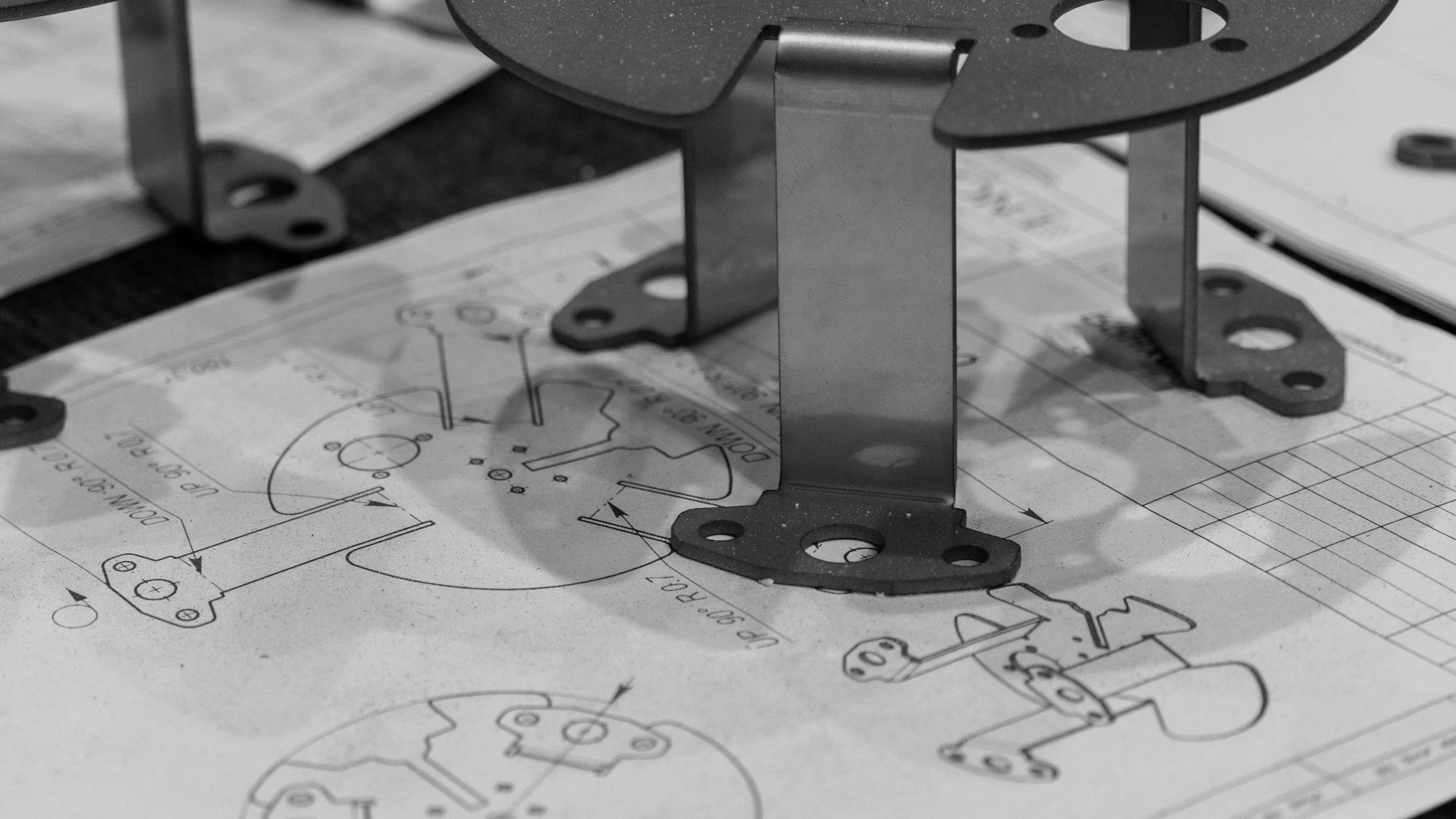
Every successful project begins with a well-engineered design. At Grantham Fabrications, our CAD design team becomes involved from the very first conversation, transforming initial concepts into fully detailed manufacturing-ready solutions.
Whether your starting point is a rough sketch on the back of a cigarette packet, an existing component, or simply an idea that needs developing, we have the experience to convert concepts into accurate 3D CAD models, manufacturing drawings and complete assemblies.
Our design capability extends from individual components to large, multi-part fabricated structures and complex mechanical assemblies. We regularly undertake reverse engineering projects, recreating obsolete or unavailable parts by analysing existing components and producing fully parametric CAD models ready for manufacture.
Design is never just about producing a drawing. Throughout every project, we apply Design for Manufacture (DfM) principles, refining components to improve manufacturability, reduce production costs, simplify assembly and enhance overall product performance without compromising functionality.
Our CAD services are available as both a standalone design consultancy and as part of a complete design-and-manufacture package, allowing customers to utilise our engineering expertise regardless of where their project sits within the development cycle.
With experience spanning industrial access systems, structural fabrications, motorsport equipment, bespoke machinery, architectural metalwork and decorative installations, our designers become involved at every stage of a project—from the initial head-scratching concept and feasibility discussions through detailed design, manufacturing support and final installation.
✔ Concept Development
✔ Reverse EngineerinG
✔ Parametric Modelling
✔ Assembly Design
✔ Weldment Design
✔ Technical Rendering
✔ Manufacturing Drawings
✔ Sheet Metal DesigN
Design Philosophy
Every design is developed with manufacturing in mind, ensuring components are not only functional but also practical, efficient and economical to produce. By applying Design for Manufacture (DfM) principles from the outset, we help reduce production time, minimise material waste and simplify fabrication without compromising performance.
Throughout the design process we consider:
✔ Material utilisation to reduce waste and improve nesting efficiency.
✔ Manufacturing processes including laser cutting, folding, machining and welding.
✔ Assembly efficiency by reducing part count and simplifying installation.
✔ Structural performance through practical, purpose-driven engineering.
✔ Serviceability to improve maintenance and future component replacement.
✔ Cost optimisation by eliminating unnecessary complexity and production time.
The result is a design that not only works on screen, but performs efficiently on the workshop floor and throughout its operational life.
SOFTWARE & FILE COMPATABILITY
3D OUTPUT
.STEP .IGES .x_t .x_b .sLDPRT .SLDASM
2D OUTPUT
.DWG .DXF .PDF
-
Fully detailed component drawings used directly for fabrication and machining.
Include critical dimensions and tolerances
Specify material grades and thickness
Define hole sizes, threads and features
Suitable for laser cutting, press braking and CNC machining
Produced for production-ready manufacture
-
Multi-component drawings showing how parts fit together within a complete system.
Define part relationships and positioning
Include fixing points and fastener locations
Support on-site and workshop assembly
Can include exploded or simplified views
Used for build accuracy and installation clarity
-
Overall system layout drawings showing size, form and spatial configuration.
Define overall dimensions and envelope sizes
Show component positioning within assemblies
Used for client approval and spatial planning
Support design coordination between disciplines
Provide project overview at system level
-
Visual breakdown of assemblies showing individual components separated for clarity.
Illustrate assembly structure and sequence
Identify part relationships clearly
Assist with build understanding and maintenance
Often used in installation and service documentation
Improves interpretation of complex assemblies
-
Structured parts list used for procurement, fabrication and assembly control.
Includes part numbers and descriptions
Specifies quantities and materials
Supports costing and production planning
Links directly to CAD model data
Ensures traceability across manufacture
Support on-site and workshop assembly
Can include exploded or simplified views
Used for build accuracy and installation clarity
-
Overall system layout drawings showing size, form and spatial configuration.
Define overall dimensions and envelope sizes
Show component positioning within assemblies
Used for client approval and spatial planning
Support design coordination between disciplines
Provide project overview at system level
cnc fibre laser
Process Overview
Every successful project begins with a well-engineered design. At Grantham Fabrications, our CAD design team becomes involved from the very first conversation, transforming initial concepts into fully detailed manufacturing-ready solutions.
Whether your starting point is a rough sketch on the back of a cigarette packet, an existing component, or simply an idea that needs developing, we have the experience to convert concepts into accurate 3D CAD models, manufacturing drawings and complete assemblies.
Our design capability extends from individual components to large, multi-part fabricated structures and complex mechanical assemblies. We regularly undertake reverse engineering projects, recreating obsolete or unavailable parts by analysing existing components and producing fully parametric CAD models ready for manufacture.
Design is never just about producing a drawing. Throughout every project, we apply Design for Manufacture (DfM) principles, refining components to improve manufacturability, reduce production costs, simplify assembly and enhance overall product performance without compromising functionality.
Our CAD services are available as both a standalone design consultancy and as part of a complete design-and-manufacture package, allowing customers to utilise our engineering expertise regardless of where their project sits within the development cycle.
With experience spanning industrial access systems, structural fabrications, motorsport equipment, bespoke machinery, architectural metalwork and decorative installations, our designers become involved at every stage of a project—from the initial head-scratching concept and feasibility discussions through detailed design, manufacturing support and final installation.
| Capability | Specification / Status |
|---|---|
| Primary CAD Software | SolidWorks (Latest) |
| 2D Output Formats | DWG, DXF |
| 3D File Formats | STEP, IGES, Parasolid, SLDPRT |
| Manufacturing Drawings | ✔ Fully Supported |
| Assembly Drawings | ✔ Fully Supported |
| Weldment Design | ✔ Structural Modelling |
| Sheet Metal Design | ✔ Flat Pattern & Form Development |
| BOM Generation | ✔ Automated Bill of Materials |
| Technical Rendering | ✔ Concept Visualisation |
| Reverse Engineering | ✔ Component Reconstruction |
| Design for Manufacture (DfM) | ✔ Fully Integrated Workflow |
✔ Concept Development
✔ Reverse EngineerinG
✔ Parametric Modelling
✔ Assembly Design
✔ Weldment Design
✔ Technical Rendering
✔ Manufacturing Drawings
✔ Sheet Metal DesigN
Design Philosophy
Every design is developed with manufacturing in mind, ensuring components are not only functional but also practical, efficient and economical to produce. By applying Design for Manufacture (DfM) principles from the outset, we help reduce production time, minimise material waste and simplify fabrication without compromising performance.
Throughout the design process we consider:
✔ Material utilisation to reduce waste and improve nesting efficiency.
✔ Manufacturing processes including laser cutting, folding, machining and welding.
✔ Assembly efficiency by reducing part count and simplifying installation.
✔ Structural performance through practical, purpose-driven engineering.
✔ Serviceability to improve maintenance and future component replacement.
✔ Cost optimisation by eliminating unnecessary complexity and production time.
The result is a design that not only works on screen, but performs efficiently on the workshop floor and throughout its operational life.
SOFTWARE & FILE COMPATABILITY
3D OUTPUT
.STEP .IGES .x_t .x_b .sLDPRT .SLDASM
-
Fully detailed component drawings used directly for fabrication and machining.
Include critical dimensions and tolerances
Specify material grades and thickness
Define hole sizes, threads and features
Suitable for laser cutting, press braking and CNC machining
Produced for production-ready manufacture
-
Multi-component drawings showing how parts fit together within a complete system.
Define part relationships and positioning
Include fixing points and fastener locations
Support on-site and workshop assembly
Can include exploded or simplified views
Used for build accuracy and installation clarity
-
Overall system layout drawings showing size, form and spatial configuration.
Define overall dimensions and envelope sizes
Show component positioning within assemblies
Used for client approval and spatial planning
Support design coordination between disciplines
Provide project overview at system level
2D OUTPUT
.DWG .DXF .PDF
-
Visual breakdown of assemblies showing individual components separated for clarity.
Illustrate assembly structure and sequence
Identify part relationships clearly
Assist with build understanding and maintenance
Often used in installation and service documentation
Improves interpretation of complex assemblies
-
Structured parts list used for procurement, fabrication and assembly control.
Includes part numbers and descriptions
Specifies quantities and materials
Supports costing and production planning
Links directly to CAD model data
Ensures traceability across manufacture
Support on-site and workshop assembly
Can include exploded or simplified views
Used for build accuracy and installation clarity
-
Overall system layout drawings showing size, form and spatial configuration.
Define overall dimensions and envelope sizes
Show component positioning within assemblies
Used for client approval and spatial planning
Support design coordination between disciplines
Provide project overview at system level
cnc plasma cutting
Process Overview
Every successful project begins with a well-engineered design. At Grantham Fabrications, our CAD design team becomes involved from the very first conversation, transforming initial concepts into fully detailed manufacturing-ready solutions.
Whether your starting point is a rough sketch on the back of a cigarette packet, an existing component, or simply an idea that needs developing, we have the experience to convert concepts into accurate 3D CAD models, manufacturing drawings and complete assemblies.
Our design capability extends from individual components to large, multi-part fabricated structures and complex mechanical assemblies. We regularly undertake reverse engineering projects, recreating obsolete or unavailable parts by analysing existing components and producing fully parametric CAD models ready for manufacture.
Design is never just about producing a drawing. Throughout every project, we apply Design for Manufacture (DfM) principles, refining components to improve manufacturability, reduce production costs, simplify assembly and enhance overall product performance without compromising functionality.
Our CAD services are available as both a standalone design consultancy and as part of a complete design-and-manufacture package, allowing customers to utilise our engineering expertise regardless of where their project sits within the development cycle.
With experience spanning industrial access systems, structural fabrications, motorsport equipment, bespoke machinery, architectural metalwork and decorative installations, our designers become involved at every stage of a project—from the initial head-scratching concept and feasibility discussions through detailed design, manufacturing support and final installation.
| Capability | Specification / Status |
|---|---|
| Primary CAD Software | SolidWorks (Latest) |
| 2D Output Formats | DWG, DXF |
| 3D File Formats | STEP, IGES, Parasolid, SLDPRT |
| Manufacturing Drawings | ✔ Fully Supported |
| Assembly Drawings | ✔ Fully Supported |
| Weldment Design | ✔ Structural Modelling |
| Sheet Metal Design | ✔ Flat Pattern & Form Development |
| BOM Generation | ✔ Automated Bill of Materials |
| Technical Rendering | ✔ Concept Visualisation |
| Reverse Engineering | ✔ Component Reconstruction |
| Design for Manufacture (DfM) | ✔ Fully Integrated Workflow |
✔ Concept Development
✔ Reverse EngineerinG
✔ Parametric Modelling
✔ Assembly Design
✔ Weldment Design
✔ Technical Rendering
✔ Manufacturing Drawings
✔ Sheet Metal DesigN
Design Philosophy
Every design is developed with manufacturing in mind, ensuring components are not only functional but also practical, efficient and economical to produce. By applying Design for Manufacture (DfM) principles from the outset, we help reduce production time, minimise material waste and simplify fabrication without compromising performance.
Throughout the design process we consider:
✔ Material utilisation to reduce waste and improve nesting efficiency.
✔ Manufacturing processes including laser cutting, folding, machining and welding.
✔ Assembly efficiency by reducing part count and simplifying installation.
✔ Structural performance through practical, purpose-driven engineering.
✔ Serviceability to improve maintenance and future component replacement.
✔ Cost optimisation by eliminating unnecessary complexity and production time.
The result is a design that not only works on screen, but performs efficiently on the workshop floor and throughout its operational life.
SOFTWARE & FILE COMPATABILITY
3D OUTPUT
.STEP .IGES .x_t .x_b .sLDPRT .SLDASM
-
Fully detailed component drawings used directly for fabrication and machining.
Include critical dimensions and tolerances
Specify material grades and thickness
Define hole sizes, threads and features
Suitable for laser cutting, press braking and CNC machining
Produced for production-ready manufacture
-
Multi-component drawings showing how parts fit together within a complete system.
Define part relationships and positioning
Include fixing points and fastener locations
Support on-site and workshop assembly
Can include exploded or simplified views
Used for build accuracy and installation clarity
-
Overall system layout drawings showing size, form and spatial configuration.
Define overall dimensions and envelope sizes
Show component positioning within assemblies
Used for client approval and spatial planning
Support design coordination between disciplines
Provide project overview at system level
2D OUTPUT
.DWG .DXF .PDF
-
Visual breakdown of assemblies showing individual components separated for clarity.
Illustrate assembly structure and sequence
Identify part relationships clearly
Assist with build understanding and maintenance
Often used in installation and service documentation
Improves interpretation of complex assemblies
-
Structured parts list used for procurement, fabrication and assembly control.
Includes part numbers and descriptions
Specifies quantities and materials
Supports costing and production planning
Links directly to CAD model data
Ensures traceability across manufacture
Support on-site and workshop assembly
Can include exploded or simplified views
Used for build accuracy and installation clarity
-
Overall system layout drawings showing size, form and spatial configuration.
Define overall dimensions and envelope sizes
Show component positioning within assemblies
Used for client approval and spatial planning
Support design coordination between disciplines
Provide project overview at system level

cnc press braking
Process Overview
Every successful project begins with a well-engineered design. At Grantham Fabrications, our CAD design team becomes involved from the very first conversation, transforming initial concepts into fully detailed manufacturing-ready solutions.
Whether your starting point is a rough sketch on the back of a cigarette packet, an existing component, or simply an idea that needs developing, we have the experience to convert concepts into accurate 3D CAD models, manufacturing drawings and complete assemblies.
Our design capability extends from individual components to large, multi-part fabricated structures and complex mechanical assemblies. We regularly undertake reverse engineering projects, recreating obsolete or unavailable parts by analysing existing components and producing fully parametric CAD models ready for manufacture.
Design is never just about producing a drawing. Throughout every project, we apply Design for Manufacture (DfM) principles, refining components to improve manufacturability, reduce production costs, simplify assembly and enhance overall product performance without compromising functionality.
Our CAD services are available as both a standalone design consultancy and as part of a complete design-and-manufacture package, allowing customers to utilise our engineering expertise regardless of where their project sits within the development cycle.
With experience spanning industrial access systems, structural fabrications, motorsport equipment, bespoke machinery, architectural metalwork and decorative installations, our designers become involved at every stage of a project—from the initial head-scratching concept and feasibility discussions through detailed design, manufacturing support and final installation.
| Capability | Specification / Status |
|---|---|
| Primary CAD Software | SolidWorks (Latest) |
| 2D Output Formats | DWG, DXF |
| 3D File Formats | STEP, IGES, Parasolid, SLDPRT |
| Manufacturing Drawings | ✔ Fully Supported |
| Assembly Drawings | ✔ Fully Supported |
| Weldment Design | ✔ Structural Modelling |
| Sheet Metal Design | ✔ Flat Pattern & Form Development |
| BOM Generation | ✔ Automated Bill of Materials |
| Technical Rendering | ✔ Concept Visualisation |
| Reverse Engineering | ✔ Component Reconstruction |
| Design for Manufacture (DfM) | ✔ Fully Integrated Workflow |
✔ Concept Development
✔ Reverse EngineerinG
✔ Parametric Modelling
✔ Assembly Design
✔ Weldment Design
✔ Technical Rendering
✔ Manufacturing Drawings
✔ Sheet Metal DesigN
Design Philosophy
Every design is developed with manufacturing in mind, ensuring components are not only functional but also practical, efficient and economical to produce. By applying Design for Manufacture (DfM) principles from the outset, we help reduce production time, minimise material waste and simplify fabrication without compromising performance.
Throughout the design process we consider:
✔ Material utilisation to reduce waste and improve nesting efficiency.
✔ Manufacturing processes including laser cutting, folding, machining and welding.
✔ Assembly efficiency by reducing part count and simplifying installation.
✔ Structural performance through practical, purpose-driven engineering.
✔ Serviceability to improve maintenance and future component replacement.
✔ Cost optimisation by eliminating unnecessary complexity and production time.
The result is a design that not only works on screen, but performs efficiently on the workshop floor and throughout its operational life.
SOFTWARE & FILE COMPATABILITY
3D OUTPUT
.STEP .IGES .x_t .x_b .sLDPRT .SLDASM
-
Fully detailed component drawings used directly for fabrication and machining.
Include critical dimensions and tolerances
Specify material grades and thickness
Define hole sizes, threads and features
Suitable for laser cutting, press braking and CNC machining
Produced for production-ready manufacture
-
Multi-component drawings showing how parts fit together within a complete system.
Define part relationships and positioning
Include fixing points and fastener locations
Support on-site and workshop assembly
Can include exploded or simplified views
Used for build accuracy and installation clarity
-
Overall system layout drawings showing size, form and spatial configuration.
Define overall dimensions and envelope sizes
Show component positioning within assemblies
Used for client approval and spatial planning
Support design coordination between disciplines
Provide project overview at system level
2D OUTPUT
.DWG .DXF .PDF
-
Visual breakdown of assemblies showing individual components separated for clarity.
Illustrate assembly structure and sequence
Identify part relationships clearly
Assist with build understanding and maintenance
Often used in installation and service documentation
Improves interpretation of complex assemblies
-
Structured parts list used for procurement, fabrication and assembly control.
Includes part numbers and descriptions
Specifies quantities and materials
Supports costing and production planning
Links directly to CAD model data
Ensures traceability across manufacture
Support on-site and workshop assembly
Can include exploded or simplified views
Used for build accuracy and installation clarity
-
Overall system layout drawings showing size, form and spatial configuration.
Define overall dimensions and envelope sizes
Show component positioning within assemblies
Used for client approval and spatial planning
Support design coordination between disciplines
Provide project overview at system level
mig welding
Process Overview
Every successful project begins with a well-engineered design. At Grantham Fabrications, our CAD design team becomes involved from the very first conversation, transforming initial concepts into fully detailed manufacturing-ready solutions.
Whether your starting point is a rough sketch on the back of a cigarette packet, an existing component, or simply an idea that needs developing, we have the experience to convert concepts into accurate 3D CAD models, manufacturing drawings and complete assemblies.
Our design capability extends from individual components to large, multi-part fabricated structures and complex mechanical assemblies. We regularly undertake reverse engineering projects, recreating obsolete or unavailable parts by analysing existing components and producing fully parametric CAD models ready for manufacture.
Design is never just about producing a drawing. Throughout every project, we apply Design for Manufacture (DfM) principles, refining components to improve manufacturability, reduce production costs, simplify assembly and enhance overall product performance without compromising functionality.
Our CAD services are available as both a standalone design consultancy and as part of a complete design-and-manufacture package, allowing customers to utilise our engineering expertise regardless of where their project sits within the development cycle.
With experience spanning industrial access systems, structural fabrications, motorsport equipment, bespoke machinery, architectural metalwork and decorative installations, our designers become involved at every stage of a project—from the initial head-scratching concept and feasibility discussions through detailed design, manufacturing support and final installation.
| Capability | Specification / Status |
|---|---|
| Primary CAD Software | SolidWorks (Latest) |
| 2D Output Formats | DWG, DXF |
| 3D File Formats | STEP, IGES, Parasolid, SLDPRT |
| Manufacturing Drawings | ✔ Fully Supported |
| Assembly Drawings | ✔ Fully Supported |
| Weldment Design | ✔ Structural Modelling |
| Sheet Metal Design | ✔ Flat Pattern & Form Development |
| BOM Generation | ✔ Automated Bill of Materials |
| Technical Rendering | ✔ Concept Visualisation |
| Reverse Engineering | ✔ Component Reconstruction |
| Design for Manufacture (DfM) | ✔ Fully Integrated Workflow |
✔ Concept Development
✔ Reverse EngineerinG
✔ Parametric Modelling
✔ Assembly Design
✔ Weldment Design
✔ Technical Rendering
✔ Manufacturing Drawings
✔ Sheet Metal DesigN
Design Philosophy
Every design is developed with manufacturing in mind, ensuring components are not only functional but also practical, efficient and economical to produce. By applying Design for Manufacture (DfM) principles from the outset, we help reduce production time, minimise material waste and simplify fabrication without compromising performance.
Throughout the design process we consider:
✔ Material utilisation to reduce waste and improve nesting efficiency.
✔ Manufacturing processes including laser cutting, folding, machining and welding.
✔ Assembly efficiency by reducing part count and simplifying installation.
✔ Structural performance through practical, purpose-driven engineering.
✔ Serviceability to improve maintenance and future component replacement.
✔ Cost optimisation by eliminating unnecessary complexity and production time.
The result is a design that not only works on screen, but performs efficiently on the workshop floor and throughout its operational life.
SOFTWARE & FILE COMPATABILITY
3D OUTPUT
.STEP .IGES .x_t .x_b .sLDPRT .SLDASM
-
Fully detailed component drawings used directly for fabrication and machining.
Include critical dimensions and tolerances
Specify material grades and thickness
Define hole sizes, threads and features
Suitable for laser cutting, press braking and CNC machining
Produced for production-ready manufacture
-
Multi-component drawings showing how parts fit together within a complete system.
Define part relationships and positioning
Include fixing points and fastener locations
Support on-site and workshop assembly
Can include exploded or simplified views
Used for build accuracy and installation clarity
-
Overall system layout drawings showing size, form and spatial configuration.
Define overall dimensions and envelope sizes
Show component positioning within assemblies
Used for client approval and spatial planning
Support design coordination between disciplines
Provide project overview at system level
2D OUTPUT
.DWG .DXF .PDF
-
Visual breakdown of assemblies showing individual components separated for clarity.
Illustrate assembly structure and sequence
Identify part relationships clearly
Assist with build understanding and maintenance
Often used in installation and service documentation
Improves interpretation of complex assemblies
-
Structured parts list used for procurement, fabrication and assembly control.
Includes part numbers and descriptions
Specifies quantities and materials
Supports costing and production planning
Links directly to CAD model data
Ensures traceability across manufacture
Support on-site and workshop assembly
Can include exploded or simplified views
Used for build accuracy and installation clarity
-
Overall system layout drawings showing size, form and spatial configuration.
Define overall dimensions and envelope sizes
Show component positioning within assemblies
Used for client approval and spatial planning
Support design coordination between disciplines
Provide project overview at system level
tig welding
Process Overview
Every successful project begins with a well-engineered design. At Grantham Fabrications, our CAD design team becomes involved from the very first conversation, transforming initial concepts into fully detailed manufacturing-ready solutions.
Whether your starting point is a rough sketch on the back of a cigarette packet, an existing component, or simply an idea that needs developing, we have the experience to convert concepts into accurate 3D CAD models, manufacturing drawings and complete assemblies.
Our design capability extends from individual components to large, multi-part fabricated structures and complex mechanical assemblies. We regularly undertake reverse engineering projects, recreating obsolete or unavailable parts by analysing existing components and producing fully parametric CAD models ready for manufacture.
Design is never just about producing a drawing. Throughout every project, we apply Design for Manufacture (DfM) principles, refining components to improve manufacturability, reduce production costs, simplify assembly and enhance overall product performance without compromising functionality.
Our CAD services are available as both a standalone design consultancy and as part of a complete design-and-manufacture package, allowing customers to utilise our engineering expertise regardless of where their project sits within the development cycle.
With experience spanning industrial access systems, structural fabrications, motorsport equipment, bespoke machinery, architectural metalwork and decorative installations, our designers become involved at every stage of a project—from the initial head-scratching concept and feasibility discussions through detailed design, manufacturing support and final installation.
| Capability | Specification / Status |
|---|---|
| Primary CAD Software | SolidWorks (Latest) |
| 2D Output Formats | DWG, DXF |
| 3D File Formats | STEP, IGES, Parasolid, SLDPRT |
| Manufacturing Drawings | ✔ Fully Supported |
| Assembly Drawings | ✔ Fully Supported |
| Weldment Design | ✔ Structural Modelling |
| Sheet Metal Design | ✔ Flat Pattern & Form Development |
| BOM Generation | ✔ Automated Bill of Materials |
| Technical Rendering | ✔ Concept Visualisation |
| Reverse Engineering | ✔ Component Reconstruction |
| Design for Manufacture (DfM) | ✔ Fully Integrated Workflow |
✔ Concept Development
✔ Reverse EngineerinG
✔ Parametric Modelling
✔ Assembly Design
✔ Weldment Design
✔ Technical Rendering
✔ Manufacturing Drawings
✔ Sheet Metal DesigN
Design Philosophy
Every design is developed with manufacturing in mind, ensuring components are not only functional but also practical, efficient and economical to produce. By applying Design for Manufacture (DfM) principles from the outset, we help reduce production time, minimise material waste and simplify fabrication without compromising performance.
Throughout the design process we consider:
✔ Material utilisation to reduce waste and improve nesting efficiency.
✔ Manufacturing processes including laser cutting, folding, machining and welding.
✔ Assembly efficiency by reducing part count and simplifying installation.
✔ Structural performance through practical, purpose-driven engineering.
✔ Serviceability to improve maintenance and future component replacement.
✔ Cost optimisation by eliminating unnecessary complexity and production time.
The result is a design that not only works on screen, but performs efficiently on the workshop floor and throughout its operational life.
SOFTWARE & FILE COMPATABILITY
3D OUTPUT
.STEP .IGES .x_t .x_b .sLDPRT .SLDASM
-
Fully detailed component drawings used directly for fabrication and machining.
Include critical dimensions and tolerances
Specify material grades and thickness
Define hole sizes, threads and features
Suitable for laser cutting, press braking and CNC machining
Produced for production-ready manufacture
-
Multi-component drawings showing how parts fit together within a complete system.
Define part relationships and positioning
Include fixing points and fastener locations
Support on-site and workshop assembly
Can include exploded or simplified views
Used for build accuracy and installation clarity
-
Overall system layout drawings showing size, form and spatial configuration.
Define overall dimensions and envelope sizes
Show component positioning within assemblies
Used for client approval and spatial planning
Support design coordination between disciplines
Provide project overview at system level
2D OUTPUT
.DWG .DXF .PDF
-
Visual breakdown of assemblies showing individual components separated for clarity.
Illustrate assembly structure and sequence
Identify part relationships clearly
Assist with build understanding and maintenance
Often used in installation and service documentation
Improves interpretation of complex assemblies
-
Structured parts list used for procurement, fabrication and assembly control.
Includes part numbers and descriptions
Specifies quantities and materials
Supports costing and production planning
Links directly to CAD model data
Ensures traceability across manufacture
Support on-site and workshop assembly
Can include exploded or simplified views
Used for build accuracy and installation clarity
-
Overall system layout drawings showing size, form and spatial configuration.
Define overall dimensions and envelope sizes
Show component positioning within assemblies
Used for client approval and spatial planning
Support design coordination between disciplines
Provide project overview at system level

Cnc turning
Process Overview
Every successful project begins with a well-engineered design. At Grantham Fabrications, our CAD design team becomes involved from the very first conversation, transforming initial concepts into fully detailed manufacturing-ready solutions.
Whether your starting point is a rough sketch on the back of a cigarette packet, an existing component, or simply an idea that needs developing, we have the experience to convert concepts into accurate 3D CAD models, manufacturing drawings and complete assemblies.
Our design capability extends from individual components to large, multi-part fabricated structures and complex mechanical assemblies. We regularly undertake reverse engineering projects, recreating obsolete or unavailable parts by analysing existing components and producing fully parametric CAD models ready for manufacture.
Design is never just about producing a drawing. Throughout every project, we apply Design for Manufacture (DfM) principles, refining components to improve manufacturability, reduce production costs, simplify assembly and enhance overall product performance without compromising functionality.
Our CAD services are available as both a standalone design consultancy and as part of a complete design-and-manufacture package, allowing customers to utilise our engineering expertise regardless of where their project sits within the development cycle.
With experience spanning industrial access systems, structural fabrications, motorsport equipment, bespoke machinery, architectural metalwork and decorative installations, our designers become involved at every stage of a project—from the initial head-scratching concept and feasibility discussions through detailed design, manufacturing support and final installation.
| Capability | Specification / Status |
|---|---|
| Primary CAD Software | SolidWorks (Latest) |
| 2D Output Formats | DWG, DXF |
| 3D File Formats | STEP, IGES, Parasolid, SLDPRT |
| Manufacturing Drawings | ✔ Fully Supported |
| Assembly Drawings | ✔ Fully Supported |
| Weldment Design | ✔ Structural Modelling |
| Sheet Metal Design | ✔ Flat Pattern & Form Development |
| BOM Generation | ✔ Automated Bill of Materials |
| Technical Rendering | ✔ Concept Visualisation |
| Reverse Engineering | ✔ Component Reconstruction |
| Design for Manufacture (DfM) | ✔ Fully Integrated Workflow |
✔ Concept Development
✔ Reverse EngineerinG
✔ Parametric Modelling
✔ Assembly Design
✔ Weldment Design
✔ Technical Rendering
✔ Manufacturing Drawings
✔ Sheet Metal DesigN
Design Philosophy
Every design is developed with manufacturing in mind, ensuring components are not only functional but also practical, efficient and economical to produce. By applying Design for Manufacture (DfM) principles from the outset, we help reduce production time, minimise material waste and simplify fabrication without compromising performance.
Throughout the design process we consider:
✔ Material utilisation to reduce waste and improve nesting efficiency.
✔ Manufacturing processes including laser cutting, folding, machining and welding.
✔ Assembly efficiency by reducing part count and simplifying installation.
✔ Structural performance through practical, purpose-driven engineering.
✔ Serviceability to improve maintenance and future component replacement.
✔ Cost optimisation by eliminating unnecessary complexity and production time.
The result is a design that not only works on screen, but performs efficiently on the workshop floor and throughout its operational life.
SOFTWARE & FILE COMPATABILITY
3D OUTPUT
.STEP .IGES .x_t .x_b .sLDPRT .SLDASM
-
Fully detailed component drawings used directly for fabrication and machining.
Include critical dimensions and tolerances
Specify material grades and thickness
Define hole sizes, threads and features
Suitable for laser cutting, press braking and CNC machining
Produced for production-ready manufacture
-
Multi-component drawings showing how parts fit together within a complete system.
Define part relationships and positioning
Include fixing points and fastener locations
Support on-site and workshop assembly
Can include exploded or simplified views
Used for build accuracy and installation clarity
-
Overall system layout drawings showing size, form and spatial configuration.
Define overall dimensions and envelope sizes
Show component positioning within assemblies
Used for client approval and spatial planning
Support design coordination between disciplines
Provide project overview at system level
2D OUTPUT
.DWG .DXF .PDF
-
Visual breakdown of assemblies showing individual components separated for clarity.
Illustrate assembly structure and sequence
Identify part relationships clearly
Assist with build understanding and maintenance
Often used in installation and service documentation
Improves interpretation of complex assemblies
-
Structured parts list used for procurement, fabrication and assembly control.
Includes part numbers and descriptions
Specifies quantities and materials
Supports costing and production planning
Links directly to CAD model data
Ensures traceability across manufacture
Support on-site and workshop assembly
Can include exploded or simplified views
Used for build accuracy and installation clarity
-
Overall system layout drawings showing size, form and spatial configuration.
Define overall dimensions and envelope sizes
Show component positioning within assemblies
Used for client approval and spatial planning
Support design coordination between disciplines
Provide project overview at system level
milling
Process Overview
Every successful project begins with a well-engineered design. At Grantham Fabrications, our CAD design team becomes involved from the very first conversation, transforming initial concepts into fully detailed manufacturing-ready solutions.
Whether your starting point is a rough sketch on the back of a cigarette packet, an existing component, or simply an idea that needs developing, we have the experience to convert concepts into accurate 3D CAD models, manufacturing drawings and complete assemblies.
Our design capability extends from individual components to large, multi-part fabricated structures and complex mechanical assemblies. We regularly undertake reverse engineering projects, recreating obsolete or unavailable parts by analysing existing components and producing fully parametric CAD models ready for manufacture.
Design is never just about producing a drawing. Throughout every project, we apply Design for Manufacture (DfM) principles, refining components to improve manufacturability, reduce production costs, simplify assembly and enhance overall product performance without compromising functionality.
Our CAD services are available as both a standalone design consultancy and as part of a complete design-and-manufacture package, allowing customers to utilise our engineering expertise regardless of where their project sits within the development cycle.
With experience spanning industrial access systems, structural fabrications, motorsport equipment, bespoke machinery, architectural metalwork and decorative installations, our designers become involved at every stage of a project—from the initial head-scratching concept and feasibility discussions through detailed design, manufacturing support and final installation.
| Capability | Specification / Status |
|---|---|
| Primary CAD Software | SolidWorks (Latest) |
| 2D Output Formats | DWG, DXF |
| 3D File Formats | STEP, IGES, Parasolid, SLDPRT |
| Manufacturing Drawings | ✔ Fully Supported |
| Assembly Drawings | ✔ Fully Supported |
| Weldment Design | ✔ Structural Modelling |
| Sheet Metal Design | ✔ Flat Pattern & Form Development |
| BOM Generation | ✔ Automated Bill of Materials |
| Technical Rendering | ✔ Concept Visualisation |
| Reverse Engineering | ✔ Component Reconstruction |
| Design for Manufacture (DfM) | ✔ Fully Integrated Workflow |
✔ Concept Development
✔ Reverse EngineerinG
✔ Parametric Modelling
✔ Assembly Design
✔ Weldment Design
✔ Technical Rendering
✔ Manufacturing Drawings
✔ Sheet Metal DesigN
Design Philosophy
Every design is developed with manufacturing in mind, ensuring components are not only functional but also practical, efficient and economical to produce. By applying Design for Manufacture (DfM) principles from the outset, we help reduce production time, minimise material waste and simplify fabrication without compromising performance.
Throughout the design process we consider:
✔ Material utilisation to reduce waste and improve nesting efficiency.
✔ Manufacturing processes including laser cutting, folding, machining and welding.
✔ Assembly efficiency by reducing part count and simplifying installation.
✔ Structural performance through practical, purpose-driven engineering.
✔ Serviceability to improve maintenance and future component replacement.
✔ Cost optimisation by eliminating unnecessary complexity and production time.
The result is a design that not only works on screen, but performs efficiently on the workshop floor and throughout its operational life.
SOFTWARE & FILE COMPATABILITY
3D OUTPUT
.STEP .IGES .x_t .x_b .sLDPRT .SLDASM
-
Fully detailed component drawings used directly for fabrication and machining.
Include critical dimensions and tolerances
Specify material grades and thickness
Define hole sizes, threads and features
Suitable for laser cutting, press braking and CNC machining
Produced for production-ready manufacture
-
Multi-component drawings showing how parts fit together within a complete system.
Define part relationships and positioning
Include fixing points and fastener locations
Support on-site and workshop assembly
Can include exploded or simplified views
Used for build accuracy and installation clarity
-
Overall system layout drawings showing size, form and spatial configuration.
Define overall dimensions and envelope sizes
Show component positioning within assemblies
Used for client approval and spatial planning
Support design coordination between disciplines
Provide project overview at system level
2D OUTPUT
.DWG .DXF .PDF
-
Visual breakdown of assemblies showing individual components separated for clarity.
Illustrate assembly structure and sequence
Identify part relationships clearly
Assist with build understanding and maintenance
Often used in installation and service documentation
Improves interpretation of complex assemblies
-
Structured parts list used for procurement, fabrication and assembly control.
Includes part numbers and descriptions
Specifies quantities and materials
Supports costing and production planning
Links directly to CAD model data
Ensures traceability across manufacture
Support on-site and workshop assembly
Can include exploded or simplified views
Used for build accuracy and installation clarity
-
Overall system layout drawings showing size, form and spatial configuration.
Define overall dimensions and envelope sizes
Show component positioning within assemblies
Used for client approval and spatial planning
Support design coordination between disciplines
Provide project overview at system level
turning
Process Overview
Every successful project begins with a well-engineered design. At Grantham Fabrications, our CAD design team becomes involved from the very first conversation, transforming initial concepts into fully detailed manufacturing-ready solutions.
Whether your starting point is a rough sketch on the back of a cigarette packet, an existing component, or simply an idea that needs developing, we have the experience to convert concepts into accurate 3D CAD models, manufacturing drawings and complete assemblies.
Our design capability extends from individual components to large, multi-part fabricated structures and complex mechanical assemblies. We regularly undertake reverse engineering projects, recreating obsolete or unavailable parts by analysing existing components and producing fully parametric CAD models ready for manufacture.
Design is never just about producing a drawing. Throughout every project, we apply Design for Manufacture (DfM) principles, refining components to improve manufacturability, reduce production costs, simplify assembly and enhance overall product performance without compromising functionality.
Our CAD services are available as both a standalone design consultancy and as part of a complete design-and-manufacture package, allowing customers to utilise our engineering expertise regardless of where their project sits within the development cycle.
With experience spanning industrial access systems, structural fabrications, motorsport equipment, bespoke machinery, architectural metalwork and decorative installations, our designers become involved at every stage of a project—from the initial head-scratching concept and feasibility discussions through detailed design, manufacturing support and final installation.
| Capability | Specification / Status |
|---|---|
| Primary CAD Software | SolidWorks (Latest) |
| 2D Output Formats | DWG, DXF |
| 3D File Formats | STEP, IGES, Parasolid, SLDPRT |
| Manufacturing Drawings | ✔ Fully Supported |
| Assembly Drawings | ✔ Fully Supported |
| Weldment Design | ✔ Structural Modelling |
| Sheet Metal Design | ✔ Flat Pattern & Form Development |
| BOM Generation | ✔ Automated Bill of Materials |
| Technical Rendering | ✔ Concept Visualisation |
| Reverse Engineering | ✔ Component Reconstruction |
| Design for Manufacture (DfM) | ✔ Fully Integrated Workflow |
✔ Concept Development
✔ Reverse EngineerinG
✔ Parametric Modelling
✔ Assembly Design
✔ Weldment Design
✔ Technical Rendering
✔ Manufacturing Drawings
✔ Sheet Metal DesigN
Design Philosophy
Every design is developed with manufacturing in mind, ensuring components are not only functional but also practical, efficient and economical to produce. By applying Design for Manufacture (DfM) principles from the outset, we help reduce production time, minimise material waste and simplify fabrication without compromising performance.
Throughout the design process we consider:
✔ Material utilisation to reduce waste and improve nesting efficiency.
✔ Manufacturing processes including laser cutting, folding, machining and welding.
✔ Assembly efficiency by reducing part count and simplifying installation.
✔ Structural performance through practical, purpose-driven engineering.
✔ Serviceability to improve maintenance and future component replacement.
✔ Cost optimisation by eliminating unnecessary complexity and production time.
The result is a design that not only works on screen, but performs efficiently on the workshop floor and throughout its operational life.
SOFTWARE & FILE COMPATABILITY
3D OUTPUT
.STEP .IGES .x_t .x_b .sLDPRT .SLDASM
-
Fully detailed component drawings used directly for fabrication and machining.
Include critical dimensions and tolerances
Specify material grades and thickness
Define hole sizes, threads and features
Suitable for laser cutting, press braking and CNC machining
Produced for production-ready manufacture
-
Multi-component drawings showing how parts fit together within a complete system.
Define part relationships and positioning
Include fixing points and fastener locations
Support on-site and workshop assembly
Can include exploded or simplified views
Used for build accuracy and installation clarity
-
Overall system layout drawings showing size, form and spatial configuration.
Define overall dimensions and envelope sizes
Show component positioning within assemblies
Used for client approval and spatial planning
Support design coordination between disciplines
Provide project overview at system level
2D OUTPUT
.DWG .DXF .PDF
-
Visual breakdown of assemblies showing individual components separated for clarity.
Illustrate assembly structure and sequence
Identify part relationships clearly
Assist with build understanding and maintenance
Often used in installation and service documentation
Improves interpretation of complex assemblies
-
Structured parts list used for procurement, fabrication and assembly control.
Includes part numbers and descriptions
Specifies quantities and materials
Supports costing and production planning
Links directly to CAD model data
Ensures traceability across manufacture
Support on-site and workshop assembly
Can include exploded or simplified views
Used for build accuracy and installation clarity
-
Overall system layout drawings showing size, form and spatial configuration.
Define overall dimensions and envelope sizes
Show component positioning within assemblies
Used for client approval and spatial planning
Support design coordination between disciplines
Provide project overview at system level
drilling
Process Overview
Every successful project begins with a well-engineered design. At Grantham Fabrications, our CAD design team becomes involved from the very first conversation, transforming initial concepts into fully detailed manufacturing-ready solutions.
Whether your starting point is a rough sketch on the back of a cigarette packet, an existing component, or simply an idea that needs developing, we have the experience to convert concepts into accurate 3D CAD models, manufacturing drawings and complete assemblies.
Our design capability extends from individual components to large, multi-part fabricated structures and complex mechanical assemblies. We regularly undertake reverse engineering projects, recreating obsolete or unavailable parts by analysing existing components and producing fully parametric CAD models ready for manufacture.
Design is never just about producing a drawing. Throughout every project, we apply Design for Manufacture (DfM) principles, refining components to improve manufacturability, reduce production costs, simplify assembly and enhance overall product performance without compromising functionality.
Our CAD services are available as both a standalone design consultancy and as part of a complete design-and-manufacture package, allowing customers to utilise our engineering expertise regardless of where their project sits within the development cycle.
With experience spanning industrial access systems, structural fabrications, motorsport equipment, bespoke machinery, architectural metalwork and decorative installations, our designers become involved at every stage of a project—from the initial head-scratching concept and feasibility discussions through detailed design, manufacturing support and final installation.
| Capability | Specification / Status |
|---|---|
| Primary CAD Software | SolidWorks (Latest) |
| 2D Output Formats | DWG, DXF |
| 3D File Formats | STEP, IGES, Parasolid, SLDPRT |
| Manufacturing Drawings | ✔ Fully Supported |
| Assembly Drawings | ✔ Fully Supported |
| Weldment Design | ✔ Structural Modelling |
| Sheet Metal Design | ✔ Flat Pattern & Form Development |
| BOM Generation | ✔ Automated Bill of Materials |
| Technical Rendering | ✔ Concept Visualisation |
| Reverse Engineering | ✔ Component Reconstruction |
| Design for Manufacture (DfM) | ✔ Fully Integrated Workflow |
✔ Concept Development
✔ Reverse EngineerinG
✔ Parametric Modelling
✔ Assembly Design
✔ Weldment Design
✔ Technical Rendering
✔ Manufacturing Drawings
✔ Sheet Metal DesigN
Design Philosophy
Every design is developed with manufacturing in mind, ensuring components are not only functional but also practical, efficient and economical to produce. By applying Design for Manufacture (DfM) principles from the outset, we help reduce production time, minimise material waste and simplify fabrication without compromising performance.
Throughout the design process we consider:
✔ Material utilisation to reduce waste and improve nesting efficiency.
✔ Manufacturing processes including laser cutting, folding, machining and welding.
✔ Assembly efficiency by reducing part count and simplifying installation.
✔ Structural performance through practical, purpose-driven engineering.
✔ Serviceability to improve maintenance and future component replacement.
✔ Cost optimisation by eliminating unnecessary complexity and production time.
The result is a design that not only works on screen, but performs efficiently on the workshop floor and throughout its operational life.
SOFTWARE & FILE COMPATABILITY
3D OUTPUT
.STEP .IGES .x_t .x_b .sLDPRT .SLDASM
-
Fully detailed component drawings used directly for fabrication and machining.
Include critical dimensions and tolerances
Specify material grades and thickness
Define hole sizes, threads and features
Suitable for laser cutting, press braking and CNC machining
Produced for production-ready manufacture
-
Multi-component drawings showing how parts fit together within a complete system.
Define part relationships and positioning
Include fixing points and fastener locations
Support on-site and workshop assembly
Can include exploded or simplified views
Used for build accuracy and installation clarity
-
Overall system layout drawings showing size, form and spatial configuration.
Define overall dimensions and envelope sizes
Show component positioning within assemblies
Used for client approval and spatial planning
Support design coordination between disciplines
Provide project overview at system level
2D OUTPUT
.DWG .DXF .PDF
-
Visual breakdown of assemblies showing individual components separated for clarity.
Illustrate assembly structure and sequence
Identify part relationships clearly
Assist with build understanding and maintenance
Often used in installation and service documentation
Improves interpretation of complex assemblies
-
Structured parts list used for procurement, fabrication and assembly control.
Includes part numbers and descriptions
Specifies quantities and materials
Supports costing and production planning
Links directly to CAD model data
Ensures traceability across manufacture
Support on-site and workshop assembly
Can include exploded or simplified views
Used for build accuracy and installation clarity
-
Overall system layout drawings showing size, form and spatial configuration.
Define overall dimensions and envelope sizes
Show component positioning within assemblies
Used for client approval and spatial planning
Support design coordination between disciplines
Provide project overview at system level

hydraulic press
Process Overview
Every successful project begins with a well-engineered design. At Grantham Fabrications, our CAD design team becomes involved from the very first conversation, transforming initial concepts into fully detailed manufacturing-ready solutions.
Whether your starting point is a rough sketch on the back of a cigarette packet, an existing component, or simply an idea that needs developing, we have the experience to convert concepts into accurate 3D CAD models, manufacturing drawings and complete assemblies.
Our design capability extends from individual components to large, multi-part fabricated structures and complex mechanical assemblies. We regularly undertake reverse engineering projects, recreating obsolete or unavailable parts by analysing existing components and producing fully parametric CAD models ready for manufacture.
Design is never just about producing a drawing. Throughout every project, we apply Design for Manufacture (DfM) principles, refining components to improve manufacturability, reduce production costs, simplify assembly and enhance overall product performance without compromising functionality.
Our CAD services are available as both a standalone design consultancy and as part of a complete design-and-manufacture package, allowing customers to utilise our engineering expertise regardless of where their project sits within the development cycle.
With experience spanning industrial access systems, structural fabrications, motorsport equipment, bespoke machinery, architectural metalwork and decorative installations, our designers become involved at every stage of a project—from the initial head-scratching concept and feasibility discussions through detailed design, manufacturing support and final installation.
| Capability | Specification / Status |
|---|---|
| Primary CAD Software | SolidWorks (Latest) |
| 2D Output Formats | DWG, DXF |
| 3D File Formats | STEP, IGES, Parasolid, SLDPRT |
| Manufacturing Drawings | ✔ Fully Supported |
| Assembly Drawings | ✔ Fully Supported |
| Weldment Design | ✔ Structural Modelling |
| Sheet Metal Design | ✔ Flat Pattern & Form Development |
| BOM Generation | ✔ Automated Bill of Materials |
| Technical Rendering | ✔ Concept Visualisation |
| Reverse Engineering | ✔ Component Reconstruction |
| Design for Manufacture (DfM) | ✔ Fully Integrated Workflow |
✔ Concept Development
✔ Reverse EngineerinG
✔ Parametric Modelling
✔ Assembly Design
✔ Weldment Design
✔ Technical Rendering
✔ Manufacturing Drawings
✔ Sheet Metal DesigN
Design Philosophy
Every design is developed with manufacturing in mind, ensuring components are not only functional but also practical, efficient and economical to produce. By applying Design for Manufacture (DfM) principles from the outset, we help reduce production time, minimise material waste and simplify fabrication without compromising performance.
Throughout the design process we consider:
✔ Material utilisation to reduce waste and improve nesting efficiency.
✔ Manufacturing processes including laser cutting, folding, machining and welding.
✔ Assembly efficiency by reducing part count and simplifying installation.
✔ Structural performance through practical, purpose-driven engineering.
✔ Serviceability to improve maintenance and future component replacement.
✔ Cost optimisation by eliminating unnecessary complexity and production time.
The result is a design that not only works on screen, but performs efficiently on the workshop floor and throughout its operational life.
SOFTWARE & FILE COMPATABILITY
3D OUTPUT
.STEP .IGES .x_t .x_b .sLDPRT .SLDASM
-
Fully detailed component drawings used directly for fabrication and machining.
Include critical dimensions and tolerances
Specify material grades and thickness
Define hole sizes, threads and features
Suitable for laser cutting, press braking and CNC machining
Produced for production-ready manufacture
-
Multi-component drawings showing how parts fit together within a complete system.
Define part relationships and positioning
Include fixing points and fastener locations
Support on-site and workshop assembly
Can include exploded or simplified views
Used for build accuracy and installation clarity
-
Overall system layout drawings showing size, form and spatial configuration.
Define overall dimensions and envelope sizes
Show component positioning within assemblies
Used for client approval and spatial planning
Support design coordination between disciplines
Provide project overview at system level
2D OUTPUT
.DWG .DXF .PDF
-
Visual breakdown of assemblies showing individual components separated for clarity.
Illustrate assembly structure and sequence
Identify part relationships clearly
Assist with build understanding and maintenance
Often used in installation and service documentation
Improves interpretation of complex assemblies
-
Structured parts list used for procurement, fabrication and assembly control.
Includes part numbers and descriptions
Specifies quantities and materials
Supports costing and production planning
Links directly to CAD model data
Ensures traceability across manufacture
Support on-site and workshop assembly
Can include exploded or simplified views
Used for build accuracy and installation clarity
-
Overall system layout drawings showing size, form and spatial configuration.
Define overall dimensions and envelope sizes
Show component positioning within assemblies
Used for client approval and spatial planning
Support design coordination between disciplines
Provide project overview at system level

rolling
Process Overview
Every successful project begins with a well-engineered design. At Grantham Fabrications, our CAD design team becomes involved from the very first conversation, transforming initial concepts into fully detailed manufacturing-ready solutions.
Whether your starting point is a rough sketch on the back of a cigarette packet, an existing component, or simply an idea that needs developing, we have the experience to convert concepts into accurate 3D CAD models, manufacturing drawings and complete assemblies.
Our design capability extends from individual components to large, multi-part fabricated structures and complex mechanical assemblies. We regularly undertake reverse engineering projects, recreating obsolete or unavailable parts by analysing existing components and producing fully parametric CAD models ready for manufacture.
Design is never just about producing a drawing. Throughout every project, we apply Design for Manufacture (DfM) principles, refining components to improve manufacturability, reduce production costs, simplify assembly and enhance overall product performance without compromising functionality.
Our CAD services are available as both a standalone design consultancy and as part of a complete design-and-manufacture package, allowing customers to utilise our engineering expertise regardless of where their project sits within the development cycle.
With experience spanning industrial access systems, structural fabrications, motorsport equipment, bespoke machinery, architectural metalwork and decorative installations, our designers become involved at every stage of a project—from the initial head-scratching concept and feasibility discussions through detailed design, manufacturing support and final installation.
| Capability | Specification / Status |
|---|---|
| Primary CAD Software | SolidWorks (Latest) |
| 2D Output Formats | DWG, DXF |
| 3D File Formats | STEP, IGES, Parasolid, SLDPRT |
| Manufacturing Drawings | ✔ Fully Supported |
| Assembly Drawings | ✔ Fully Supported |
| Weldment Design | ✔ Structural Modelling |
| Sheet Metal Design | ✔ Flat Pattern & Form Development |
| BOM Generation | ✔ Automated Bill of Materials |
| Technical Rendering | ✔ Concept Visualisation |
| Reverse Engineering | ✔ Component Reconstruction |
| Design for Manufacture (DfM) | ✔ Fully Integrated Workflow |
✔ Concept Development
✔ Reverse EngineerinG
✔ Parametric Modelling
✔ Assembly Design
✔ Weldment Design
✔ Technical Rendering
✔ Manufacturing Drawings
✔ Sheet Metal DesigN
Design Philosophy
Every design is developed with manufacturing in mind, ensuring components are not only functional but also practical, efficient and economical to produce. By applying Design for Manufacture (DfM) principles from the outset, we help reduce production time, minimise material waste and simplify fabrication without compromising performance.
Throughout the design process we consider:
✔ Material utilisation to reduce waste and improve nesting efficiency.
✔ Manufacturing processes including laser cutting, folding, machining and welding.
✔ Assembly efficiency by reducing part count and simplifying installation.
✔ Structural performance through practical, purpose-driven engineering.
✔ Serviceability to improve maintenance and future component replacement.
✔ Cost optimisation by eliminating unnecessary complexity and production time.
The result is a design that not only works on screen, but performs efficiently on the workshop floor and throughout its operational life.
SOFTWARE & FILE COMPATABILITY
3D OUTPUT
.STEP .IGES .x_t .x_b .sLDPRT .SLDASM
-
Fully detailed component drawings used directly for fabrication and machining.
Include critical dimensions and tolerances
Specify material grades and thickness
Define hole sizes, threads and features
Suitable for laser cutting, press braking and CNC machining
Produced for production-ready manufacture
-
Multi-component drawings showing how parts fit together within a complete system.
Define part relationships and positioning
Include fixing points and fastener locations
Support on-site and workshop assembly
Can include exploded or simplified views
Used for build accuracy and installation clarity
-
Overall system layout drawings showing size, form and spatial configuration.
Define overall dimensions and envelope sizes
Show component positioning within assemblies
Used for client approval and spatial planning
Support design coordination between disciplines
Provide project overview at system level
2D OUTPUT
.DWG .DXF .PDF
-
Visual breakdown of assemblies showing individual components separated for clarity.
Illustrate assembly structure and sequence
Identify part relationships clearly
Assist with build understanding and maintenance
Often used in installation and service documentation
Improves interpretation of complex assemblies
-
Structured parts list used for procurement, fabrication and assembly control.
Includes part numbers and descriptions
Specifies quantities and materials
Supports costing and production planning
Links directly to CAD model data
Ensures traceability across manufacture
Support on-site and workshop assembly
Can include exploded or simplified views
Used for build accuracy and installation clarity
-
Overall system layout drawings showing size, form and spatial configuration.
Define overall dimensions and envelope sizes
Show component positioning within assemblies
Used for client approval and spatial planning
Support design coordination between disciplines
Provide project overview at system level
guillotine
Process Overview
Every successful project begins with a well-engineered design. At Grantham Fabrications, our CAD design team becomes involved from the very first conversation, transforming initial concepts into fully detailed manufacturing-ready solutions.
Whether your starting point is a rough sketch on the back of a cigarette packet, an existing component, or simply an idea that needs developing, we have the experience to convert concepts into accurate 3D CAD models, manufacturing drawings and complete assemblies.
Our design capability extends from individual components to large, multi-part fabricated structures and complex mechanical assemblies. We regularly undertake reverse engineering projects, recreating obsolete or unavailable parts by analysing existing components and producing fully parametric CAD models ready for manufacture.
Design is never just about producing a drawing. Throughout every project, we apply Design for Manufacture (DfM) principles, refining components to improve manufacturability, reduce production costs, simplify assembly and enhance overall product performance without compromising functionality.
Our CAD services are available as both a standalone design consultancy and as part of a complete design-and-manufacture package, allowing customers to utilise our engineering expertise regardless of where their project sits within the development cycle.
With experience spanning industrial access systems, structural fabrications, motorsport equipment, bespoke machinery, architectural metalwork and decorative installations, our designers become involved at every stage of a project—from the initial head-scratching concept and feasibility discussions through detailed design, manufacturing support and final installation.
| Capability | Specification / Status |
|---|---|
| Primary CAD Software | SolidWorks (Latest) |
| 2D Output Formats | DWG, DXF |
| 3D File Formats | STEP, IGES, Parasolid, SLDPRT |
| Manufacturing Drawings | ✔ Fully Supported |
| Assembly Drawings | ✔ Fully Supported |
| Weldment Design | ✔ Structural Modelling |
| Sheet Metal Design | ✔ Flat Pattern & Form Development |
| BOM Generation | ✔ Automated Bill of Materials |
| Technical Rendering | ✔ Concept Visualisation |
| Reverse Engineering | ✔ Component Reconstruction |
| Design for Manufacture (DfM) | ✔ Fully Integrated Workflow |
✔ Concept Development
✔ Reverse EngineerinG
✔ Parametric Modelling
✔ Assembly Design
✔ Weldment Design
✔ Technical Rendering
✔ Manufacturing Drawings
✔ Sheet Metal DesigN
Design Philosophy
Every design is developed with manufacturing in mind, ensuring components are not only functional but also practical, efficient and economical to produce. By applying Design for Manufacture (DfM) principles from the outset, we help reduce production time, minimise material waste and simplify fabrication without compromising performance.
Throughout the design process we consider:
✔ Material utilisation to reduce waste and improve nesting efficiency.
✔ Manufacturing processes including laser cutting, folding, machining and welding.
✔ Assembly efficiency by reducing part count and simplifying installation.
✔ Structural performance through practical, purpose-driven engineering.
✔ Serviceability to improve maintenance and future component replacement.
✔ Cost optimisation by eliminating unnecessary complexity and production time.
The result is a design that not only works on screen, but performs efficiently on the workshop floor and throughout its operational life.
SOFTWARE & FILE COMPATABILITY
3D OUTPUT
.STEP .IGES .x_t .x_b .sLDPRT .SLDASM
-
Fully detailed component drawings used directly for fabrication and machining.
Include critical dimensions and tolerances
Specify material grades and thickness
Define hole sizes, threads and features
Suitable for laser cutting, press braking and CNC machining
Produced for production-ready manufacture
-
Multi-component drawings showing how parts fit together within a complete system.
Define part relationships and positioning
Include fixing points and fastener locations
Support on-site and workshop assembly
Can include exploded or simplified views
Used for build accuracy and installation clarity
-
Overall system layout drawings showing size, form and spatial configuration.
Define overall dimensions and envelope sizes
Show component positioning within assemblies
Used for client approval and spatial planning
Support design coordination between disciplines
Provide project overview at system level
2D OUTPUT
.DWG .DXF .PDF
-
Visual breakdown of assemblies showing individual components separated for clarity.
Illustrate assembly structure and sequence
Identify part relationships clearly
Assist with build understanding and maintenance
Often used in installation and service documentation
Improves interpretation of complex assemblies
-
Structured parts list used for procurement, fabrication and assembly control.
Includes part numbers and descriptions
Specifies quantities and materials
Supports costing and production planning
Links directly to CAD model data
Ensures traceability across manufacture
Support on-site and workshop assembly
Can include exploded or simplified views
Used for build accuracy and installation clarity
-
Overall system layout drawings showing size, form and spatial configuration.
Define overall dimensions and envelope sizes
Show component positioning within assemblies
Used for client approval and spatial planning
Support design coordination between disciplines
Provide project overview at system level

sawing
Process Overview
Every successful project begins with a well-engineered design. At Grantham Fabrications, our CAD design team becomes involved from the very first conversation, transforming initial concepts into fully detailed manufacturing-ready solutions.
Whether your starting point is a rough sketch on the back of a cigarette packet, an existing component, or simply an idea that needs developing, we have the experience to convert concepts into accurate 3D CAD models, manufacturing drawings and complete assemblies.
Our design capability extends from individual components to large, multi-part fabricated structures and complex mechanical assemblies. We regularly undertake reverse engineering projects, recreating obsolete or unavailable parts by analysing existing components and producing fully parametric CAD models ready for manufacture.
Design is never just about producing a drawing. Throughout every project, we apply Design for Manufacture (DfM) principles, refining components to improve manufacturability, reduce production costs, simplify assembly and enhance overall product performance without compromising functionality.
Our CAD services are available as both a standalone design consultancy and as part of a complete design-and-manufacture package, allowing customers to utilise our engineering expertise regardless of where their project sits within the development cycle.
With experience spanning industrial access systems, structural fabrications, motorsport equipment, bespoke machinery, architectural metalwork and decorative installations, our designers become involved at every stage of a project—from the initial head-scratching concept and feasibility discussions through detailed design, manufacturing support and final installation.
| Capability | Specification / Status |
|---|---|
| Primary CAD Software | SolidWorks (Latest) |
| 2D Output Formats | DWG, DXF |
| 3D File Formats | STEP, IGES, Parasolid, SLDPRT |
| Manufacturing Drawings | ✔ Fully Supported |
| Assembly Drawings | ✔ Fully Supported |
| Weldment Design | ✔ Structural Modelling |
| Sheet Metal Design | ✔ Flat Pattern & Form Development |
| BOM Generation | ✔ Automated Bill of Materials |
| Technical Rendering | ✔ Concept Visualisation |
| Reverse Engineering | ✔ Component Reconstruction |
| Design for Manufacture (DfM) | ✔ Fully Integrated Workflow |
✔ Concept Development
✔ Reverse EngineerinG
✔ Parametric Modelling
✔ Assembly Design
✔ Weldment Design
✔ Technical Rendering
✔ Manufacturing Drawings
✔ Sheet Metal DesigN
Design Philosophy
Every design is developed with manufacturing in mind, ensuring components are not only functional but also practical, efficient and economical to produce. By applying Design for Manufacture (DfM) principles from the outset, we help reduce production time, minimise material waste and simplify fabrication without compromising performance.
Throughout the design process we consider:
✔ Material utilisation to reduce waste and improve nesting efficiency.
✔ Manufacturing processes including laser cutting, folding, machining and welding.
✔ Assembly efficiency by reducing part count and simplifying installation.
✔ Structural performance through practical, purpose-driven engineering.
✔ Serviceability to improve maintenance and future component replacement.
✔ Cost optimisation by eliminating unnecessary complexity and production time.
The result is a design that not only works on screen, but performs efficiently on the workshop floor and throughout its operational life.
SOFTWARE & FILE COMPATABILITY
3D OUTPUT
.STEP .IGES .x_t .x_b .sLDPRT .SLDASM
-
Fully detailed component drawings used directly for fabrication and machining.
Include critical dimensions and tolerances
Specify material grades and thickness
Define hole sizes, threads and features
Suitable for laser cutting, press braking and CNC machining
Produced for production-ready manufacture
-
Multi-component drawings showing how parts fit together within a complete system.
Define part relationships and positioning
Include fixing points and fastener locations
Support on-site and workshop assembly
Can include exploded or simplified views
Used for build accuracy and installation clarity
-
Overall system layout drawings showing size, form and spatial configuration.
Define overall dimensions and envelope sizes
Show component positioning within assemblies
Used for client approval and spatial planning
Support design coordination between disciplines
Provide project overview at system level
2D OUTPUT
.DWG .DXF .PDF
-
Visual breakdown of assemblies showing individual components separated for clarity.
Illustrate assembly structure and sequence
Identify part relationships clearly
Assist with build understanding and maintenance
Often used in installation and service documentation
Improves interpretation of complex assemblies
-
Structured parts list used for procurement, fabrication and assembly control.
Includes part numbers and descriptions
Specifies quantities and materials
Supports costing and production planning
Links directly to CAD model data
Ensures traceability across manufacture
Support on-site and workshop assembly
Can include exploded or simplified views
Used for build accuracy and installation clarity
-
Overall system layout drawings showing size, form and spatial configuration.
Define overall dimensions and envelope sizes
Show component positioning within assemblies
Used for client approval and spatial planning
Support design coordination between disciplines
Provide project overview at system level
paint spraying
Process Overview
Every successful project begins with a well-engineered design. At Grantham Fabrications, our CAD design team becomes involved from the very first conversation, transforming initial concepts into fully detailed manufacturing-ready solutions.
Whether your starting point is a rough sketch on the back of a cigarette packet, an existing component, or simply an idea that needs developing, we have the experience to convert concepts into accurate 3D CAD models, manufacturing drawings and complete assemblies.
Our design capability extends from individual components to large, multi-part fabricated structures and complex mechanical assemblies. We regularly undertake reverse engineering projects, recreating obsolete or unavailable parts by analysing existing components and producing fully parametric CAD models ready for manufacture.
Design is never just about producing a drawing. Throughout every project, we apply Design for Manufacture (DfM) principles, refining components to improve manufacturability, reduce production costs, simplify assembly and enhance overall product performance without compromising functionality.
Our CAD services are available as both a standalone design consultancy and as part of a complete design-and-manufacture package, allowing customers to utilise our engineering expertise regardless of where their project sits within the development cycle.
With experience spanning industrial access systems, structural fabrications, motorsport equipment, bespoke machinery, architectural metalwork and decorative installations, our designers become involved at every stage of a project—from the initial head-scratching concept and feasibility discussions through detailed design, manufacturing support and final installation.
| Capability | Specification / Status |
|---|---|
| Primary CAD Software | SolidWorks (Latest) |
| 2D Output Formats | DWG, DXF |
| 3D File Formats | STEP, IGES, Parasolid, SLDPRT |
| Manufacturing Drawings | ✔ Fully Supported |
| Assembly Drawings | ✔ Fully Supported |
| Weldment Design | ✔ Structural Modelling |
| Sheet Metal Design | ✔ Flat Pattern & Form Development |
| BOM Generation | ✔ Automated Bill of Materials |
| Technical Rendering | ✔ Concept Visualisation |
| Reverse Engineering | ✔ Component Reconstruction |
| Design for Manufacture (DfM) | ✔ Fully Integrated Workflow |
✔ Concept Development
✔ Reverse EngineerinG
✔ Parametric Modelling
✔ Assembly Design
✔ Weldment Design
✔ Technical Rendering
✔ Manufacturing Drawings
✔ Sheet Metal DesigN
Design Philosophy
Every design is developed with manufacturing in mind, ensuring components are not only functional but also practical, efficient and economical to produce. By applying Design for Manufacture (DfM) principles from the outset, we help reduce production time, minimise material waste and simplify fabrication without compromising performance.
Throughout the design process we consider:
✔ Material utilisation to reduce waste and improve nesting efficiency.
✔ Manufacturing processes including laser cutting, folding, machining and welding.
✔ Assembly efficiency by reducing part count and simplifying installation.
✔ Structural performance through practical, purpose-driven engineering.
✔ Serviceability to improve maintenance and future component replacement.
✔ Cost optimisation by eliminating unnecessary complexity and production time.
The result is a design that not only works on screen, but performs efficiently on the workshop floor and throughout its operational life.
SOFTWARE & FILE COMPATABILITY
3D OUTPUT
.STEP .IGES .x_t .x_b .sLDPRT .SLDASM
-
Fully detailed component drawings used directly for fabrication and machining.
Include critical dimensions and tolerances
Specify material grades and thickness
Define hole sizes, threads and features
Suitable for laser cutting, press braking and CNC machining
Produced for production-ready manufacture
-
Multi-component drawings showing how parts fit together within a complete system.
Define part relationships and positioning
Include fixing points and fastener locations
Support on-site and workshop assembly
Can include exploded or simplified views
Used for build accuracy and installation clarity
-
Overall system layout drawings showing size, form and spatial configuration.
Define overall dimensions and envelope sizes
Show component positioning within assemblies
Used for client approval and spatial planning
Support design coordination between disciplines
Provide project overview at system level
2D OUTPUT
.DWG .DXF .PDF
-
Visual breakdown of assemblies showing individual components separated for clarity.
Illustrate assembly structure and sequence
Identify part relationships clearly
Assist with build understanding and maintenance
Often used in installation and service documentation
Improves interpretation of complex assemblies
-
Structured parts list used for procurement, fabrication and assembly control.
Includes part numbers and descriptions
Specifies quantities and materials
Supports costing and production planning
Links directly to CAD model data
Ensures traceability across manufacture
Support on-site and workshop assembly
Can include exploded or simplified views
Used for build accuracy and installation clarity
-
Overall system layout drawings showing size, form and spatial configuration.
Define overall dimensions and envelope sizes
Show component positioning within assemblies
Used for client approval and spatial planning
Support design coordination between disciplines
Provide project overview at system level
gantry crane
Process Overview
Every successful project begins with a well-engineered design. At Grantham Fabrications, our CAD design team becomes involved from the very first conversation, transforming initial concepts into fully detailed manufacturing-ready solutions.
Whether your starting point is a rough sketch on the back of a cigarette packet, an existing component, or simply an idea that needs developing, we have the experience to convert concepts into accurate 3D CAD models, manufacturing drawings and complete assemblies.
Our design capability extends from individual components to large, multi-part fabricated structures and complex mechanical assemblies. We regularly undertake reverse engineering projects, recreating obsolete or unavailable parts by analysing existing components and producing fully parametric CAD models ready for manufacture.
Design is never just about producing a drawing. Throughout every project, we apply Design for Manufacture (DfM) principles, refining components to improve manufacturability, reduce production costs, simplify assembly and enhance overall product performance without compromising functionality.
Our CAD services are available as both a standalone design consultancy and as part of a complete design-and-manufacture package, allowing customers to utilise our engineering expertise regardless of where their project sits within the development cycle.
With experience spanning industrial access systems, structural fabrications, motorsport equipment, bespoke machinery, architectural metalwork and decorative installations, our designers become involved at every stage of a project—from the initial head-scratching concept and feasibility discussions through detailed design, manufacturing support and final installation.
| Capability | Specification / Status |
|---|---|
| Primary CAD Software | SolidWorks (Latest) |
| 2D Output Formats | DWG, DXF |
| 3D File Formats | STEP, IGES, Parasolid, SLDPRT |
| Manufacturing Drawings | ✔ Fully Supported |
| Assembly Drawings | ✔ Fully Supported |
| Weldment Design | ✔ Structural Modelling |
| Sheet Metal Design | ✔ Flat Pattern & Form Development |
| BOM Generation | ✔ Automated Bill of Materials |
| Technical Rendering | ✔ Concept Visualisation |
| Reverse Engineering | ✔ Component Reconstruction |
| Design for Manufacture (DfM) | ✔ Fully Integrated Workflow |
✔ Concept Development
✔ Reverse EngineerinG
✔ Parametric Modelling
✔ Assembly Design
✔ Weldment Design
✔ Technical Rendering
✔ Manufacturing Drawings
✔ Sheet Metal DesigN
Design Philosophy
Every design is developed with manufacturing in mind, ensuring components are not only functional but also practical, efficient and economical to produce. By applying Design for Manufacture (DfM) principles from the outset, we help reduce production time, minimise material waste and simplify fabrication without compromising performance.
Throughout the design process we consider:
✔ Material utilisation to reduce waste and improve nesting efficiency.
✔ Manufacturing processes including laser cutting, folding, machining and welding.
✔ Assembly efficiency by reducing part count and simplifying installation.
✔ Structural performance through practical, purpose-driven engineering.
✔ Serviceability to improve maintenance and future component replacement.
✔ Cost optimisation by eliminating unnecessary complexity and production time.
The result is a design that not only works on screen, but performs efficiently on the workshop floor and throughout its operational life.
SOFTWARE & FILE COMPATABILITY
3D OUTPUT
.STEP .IGES .x_t .x_b .sLDPRT .SLDASM
-
Fully detailed component drawings used directly for fabrication and machining.
Include critical dimensions and tolerances
Specify material grades and thickness
Define hole sizes, threads and features
Suitable for laser cutting, press braking and CNC machining
Produced for production-ready manufacture
-
Multi-component drawings showing how parts fit together within a complete system.
Define part relationships and positioning
Include fixing points and fastener locations
Support on-site and workshop assembly
Can include exploded or simplified views
Used for build accuracy and installation clarity
-
Overall system layout drawings showing size, form and spatial configuration.
Define overall dimensions and envelope sizes
Show component positioning within assemblies
Used for client approval and spatial planning
Support design coordination between disciplines
Provide project overview at system level
2D OUTPUT
.DWG .DXF .PDF
-
Visual breakdown of assemblies showing individual components separated for clarity.
Illustrate assembly structure and sequence
Identify part relationships clearly
Assist with build understanding and maintenance
Often used in installation and service documentation
Improves interpretation of complex assemblies
-
Structured parts list used for procurement, fabrication and assembly control.
Includes part numbers and descriptions
Specifies quantities and materials
Supports costing and production planning
Links directly to CAD model data
Ensures traceability across manufacture
Support on-site and workshop assembly
Can include exploded or simplified views
Used for build accuracy and installation clarity
-
Overall system layout drawings showing size, form and spatial configuration.
Define overall dimensions and envelope sizes
Show component positioning within assemblies
Used for client approval and spatial planning
Support design coordination between disciplines
Provide project overview at system level
forklift
Process Overview
Every successful project begins with a well-engineered design. At Grantham Fabrications, our CAD design team becomes involved from the very first conversation, transforming initial concepts into fully detailed manufacturing-ready solutions.
Whether your starting point is a rough sketch on the back of a cigarette packet, an existing component, or simply an idea that needs developing, we have the experience to convert concepts into accurate 3D CAD models, manufacturing drawings and complete assemblies.
Our design capability extends from individual components to large, multi-part fabricated structures and complex mechanical assemblies. We regularly undertake reverse engineering projects, recreating obsolete or unavailable parts by analysing existing components and producing fully parametric CAD models ready for manufacture.
Design is never just about producing a drawing. Throughout every project, we apply Design for Manufacture (DfM) principles, refining components to improve manufacturability, reduce production costs, simplify assembly and enhance overall product performance without compromising functionality.
Our CAD services are available as both a standalone design consultancy and as part of a complete design-and-manufacture package, allowing customers to utilise our engineering expertise regardless of where their project sits within the development cycle.
With experience spanning industrial access systems, structural fabrications, motorsport equipment, bespoke machinery, architectural metalwork and decorative installations, our designers become involved at every stage of a project—from the initial head-scratching concept and feasibility discussions through detailed design, manufacturing support and final installation.
| Capability | Specification / Status |
|---|---|
| Primary CAD Software | SolidWorks (Latest) |
| 2D Output Formats | DWG, DXF |
| 3D File Formats | STEP, IGES, Parasolid, SLDPRT |
| Manufacturing Drawings | ✔ Fully Supported |
| Assembly Drawings | ✔ Fully Supported |
| Weldment Design | ✔ Structural Modelling |
| Sheet Metal Design | ✔ Flat Pattern & Form Development |
| BOM Generation | ✔ Automated Bill of Materials |
| Technical Rendering | ✔ Concept Visualisation |
| Reverse Engineering | ✔ Component Reconstruction |
| Design for Manufacture (DfM) | ✔ Fully Integrated Workflow |
✔ Concept Development
✔ Reverse EngineerinG
✔ Parametric Modelling
✔ Assembly Design
✔ Weldment Design
✔ Technical Rendering
✔ Manufacturing Drawings
✔ Sheet Metal DesigN
Design Philosophy
Every design is developed with manufacturing in mind, ensuring components are not only functional but also practical, efficient and economical to produce. By applying Design for Manufacture (DfM) principles from the outset, we help reduce production time, minimise material waste and simplify fabrication without compromising performance.
Throughout the design process we consider:
✔ Material utilisation to reduce waste and improve nesting efficiency.
✔ Manufacturing processes including laser cutting, folding, machining and welding.
✔ Assembly efficiency by reducing part count and simplifying installation.
✔ Structural performance through practical, purpose-driven engineering.
✔ Serviceability to improve maintenance and future component replacement.
✔ Cost optimisation by eliminating unnecessary complexity and production time.
The result is a design that not only works on screen, but performs efficiently on the workshop floor and throughout its operational life.
SOFTWARE & FILE COMPATABILITY
3D OUTPUT
.STEP .IGES .x_t .x_b .sLDPRT .SLDASM
-
Fully detailed component drawings used directly for fabrication and machining.
Include critical dimensions and tolerances
Specify material grades and thickness
Define hole sizes, threads and features
Suitable for laser cutting, press braking and CNC machining
Produced for production-ready manufacture
-
Multi-component drawings showing how parts fit together within a complete system.
Define part relationships and positioning
Include fixing points and fastener locations
Support on-site and workshop assembly
Can include exploded or simplified views
Used for build accuracy and installation clarity
-
Overall system layout drawings showing size, form and spatial configuration.
Define overall dimensions and envelope sizes
Show component positioning within assemblies
Used for client approval and spatial planning
Support design coordination between disciplines
Provide project overview at system level
2D OUTPUT
.DWG .DXF .PDF
-
Visual breakdown of assemblies showing individual components separated for clarity.
Illustrate assembly structure and sequence
Identify part relationships clearly
Assist with build understanding and maintenance
Often used in installation and service documentation
Improves interpretation of complex assemblies
-
Structured parts list used for procurement, fabrication and assembly control.
Includes part numbers and descriptions
Specifies quantities and materials
Supports costing and production planning
Links directly to CAD model data
Ensures traceability across manufacture
Support on-site and workshop assembly
Can include exploded or simplified views
Used for build accuracy and installation clarity
-
Overall system layout drawings showing size, form and spatial configuration.
Define overall dimensions and envelope sizes
Show component positioning within assemblies
Used for client approval and spatial planning
Support design coordination between disciplines
Provide project overview at system level
delivery & Collection
Process Overview
Every successful project begins with a well-engineered design. At Grantham Fabrications, our CAD design team becomes involved from the very first conversation, transforming initial concepts into fully detailed manufacturing-ready solutions.
Whether your starting point is a rough sketch on the back of a cigarette packet, an existing component, or simply an idea that needs developing, we have the experience to convert concepts into accurate 3D CAD models, manufacturing drawings and complete assemblies.
Our design capability extends from individual components to large, multi-part fabricated structures and complex mechanical assemblies. We regularly undertake reverse engineering projects, recreating obsolete or unavailable parts by analysing existing components and producing fully parametric CAD models ready for manufacture.
Design is never just about producing a drawing. Throughout every project, we apply Design for Manufacture (DfM) principles, refining components to improve manufacturability, reduce production costs, simplify assembly and enhance overall product performance without compromising functionality.
Our CAD services are available as both a standalone design consultancy and as part of a complete design-and-manufacture package, allowing customers to utilise our engineering expertise regardless of where their project sits within the development cycle.
With experience spanning industrial access systems, structural fabrications, motorsport equipment, bespoke machinery, architectural metalwork and decorative installations, our designers become involved at every stage of a project—from the initial head-scratching concept and feasibility discussions through detailed design, manufacturing support and final installation.
| Capability | Specification / Status |
|---|---|
| Primary CAD Software | SolidWorks (Latest) |
| 2D Output Formats | DWG, DXF |
| 3D File Formats | STEP, IGES, Parasolid, SLDPRT |
| Manufacturing Drawings | ✔ Fully Supported |
| Assembly Drawings | ✔ Fully Supported |
| Weldment Design | ✔ Structural Modelling |
| Sheet Metal Design | ✔ Flat Pattern & Form Development |
| BOM Generation | ✔ Automated Bill of Materials |
| Technical Rendering | ✔ Concept Visualisation |
| Reverse Engineering | ✔ Component Reconstruction |
| Design for Manufacture (DfM) | ✔ Fully Integrated Workflow |
✔ Concept Development
✔ Reverse EngineerinG
✔ Parametric Modelling
✔ Assembly Design
✔ Weldment Design
✔ Technical Rendering
✔ Manufacturing Drawings
✔ Sheet Metal DesigN
Design Philosophy
Every design is developed with manufacturing in mind, ensuring components are not only functional but also practical, efficient and economical to produce. By applying Design for Manufacture (DfM) principles from the outset, we help reduce production time, minimise material waste and simplify fabrication without compromising performance.
Throughout the design process we consider:
✔ Material utilisation to reduce waste and improve nesting efficiency.
✔ Manufacturing processes including laser cutting, folding, machining and welding.
✔ Assembly efficiency by reducing part count and simplifying installation.
✔ Structural performance through practical, purpose-driven engineering.
✔ Serviceability to improve maintenance and future component replacement.
✔ Cost optimisation by eliminating unnecessary complexity and production time.
The result is a design that not only works on screen, but performs efficiently on the workshop floor and throughout its operational life.
SOFTWARE & FILE COMPATABILITY
3D OUTPUT
.STEP .IGES .x_t .x_b .sLDPRT .SLDASM
-
Fully detailed component drawings used directly for fabrication and machining.
Include critical dimensions and tolerances
Specify material grades and thickness
Define hole sizes, threads and features
Suitable for laser cutting, press braking and CNC machining
Produced for production-ready manufacture
-
Multi-component drawings showing how parts fit together within a complete system.
Define part relationships and positioning
Include fixing points and fastener locations
Support on-site and workshop assembly
Can include exploded or simplified views
Used for build accuracy and installation clarity
-
Overall system layout drawings showing size, form and spatial configuration.
Define overall dimensions and envelope sizes
Show component positioning within assemblies
Used for client approval and spatial planning
Support design coordination between disciplines
Provide project overview at system level
2D OUTPUT
.DWG .DXF .PDF
-
Visual breakdown of assemblies showing individual components separated for clarity.
Illustrate assembly structure and sequence
Identify part relationships clearly
Assist with build understanding and maintenance
Often used in installation and service documentation
Improves interpretation of complex assemblies
-
Structured parts list used for procurement, fabrication and assembly control.
Includes part numbers and descriptions
Specifies quantities and materials
Supports costing and production planning
Links directly to CAD model data
Ensures traceability across manufacture
Support on-site and workshop assembly
Can include exploded or simplified views
Used for build accuracy and installation clarity
-
Overall system layout drawings showing size, form and spatial configuration.
Define overall dimensions and envelope sizes
Show component positioning within assemblies
Used for client approval and spatial planning
Support design coordination between disciplines
Provide project overview at system level
structural steel
Process Overview
Every successful project begins with a well-engineered design. At Grantham Fabrications, our CAD design team becomes involved from the very first conversation, transforming initial concepts into fully detailed manufacturing-ready solutions.
Whether your starting point is a rough sketch on the back of a cigarette packet, an existing component, or simply an idea that needs developing, we have the experience to convert concepts into accurate 3D CAD models, manufacturing drawings and complete assemblies.
Our design capability extends from individual components to large, multi-part fabricated structures and complex mechanical assemblies. We regularly undertake reverse engineering projects, recreating obsolete or unavailable parts by analysing existing components and producing fully parametric CAD models ready for manufacture.
Design is never just about producing a drawing. Throughout every project, we apply Design for Manufacture (DfM) principles, refining components to improve manufacturability, reduce production costs, simplify assembly and enhance overall product performance without compromising functionality.
Our CAD services are available as both a standalone design consultancy and as part of a complete design-and-manufacture package, allowing customers to utilise our engineering expertise regardless of where their project sits within the development cycle.
With experience spanning industrial access systems, structural fabrications, motorsport equipment, bespoke machinery, architectural metalwork and decorative installations, our designers become involved at every stage of a project—from the initial head-scratching concept and feasibility discussions through detailed design, manufacturing support and final installation.
| Capability | Specification / Status |
|---|---|
| Primary CAD Software | SolidWorks (Latest) |
| 2D Output Formats | DWG, DXF |
| 3D File Formats | STEP, IGES, Parasolid, SLDPRT |
| Manufacturing Drawings | ✔ Fully Supported |
| Assembly Drawings | ✔ Fully Supported |
| Weldment Design | ✔ Structural Modelling |
| Sheet Metal Design | ✔ Flat Pattern & Form Development |
| BOM Generation | ✔ Automated Bill of Materials |
| Technical Rendering | ✔ Concept Visualisation |
| Reverse Engineering | ✔ Component Reconstruction |
| Design for Manufacture (DfM) | ✔ Fully Integrated Workflow |
✔ Concept Development
✔ Reverse EngineerinG
✔ Parametric Modelling
✔ Assembly Design
✔ Weldment Design
✔ Technical Rendering
✔ Manufacturing Drawings
✔ Sheet Metal DesigN
Design Philosophy
Every design is developed with manufacturing in mind, ensuring components are not only functional but also practical, efficient and economical to produce. By applying Design for Manufacture (DfM) principles from the outset, we help reduce production time, minimise material waste and simplify fabrication without compromising performance.
Throughout the design process we consider:
✔ Material utilisation to reduce waste and improve nesting efficiency.
✔ Manufacturing processes including laser cutting, folding, machining and welding.
✔ Assembly efficiency by reducing part count and simplifying installation.
✔ Structural performance through practical, purpose-driven engineering.
✔ Serviceability to improve maintenance and future component replacement.
✔ Cost optimisation by eliminating unnecessary complexity and production time.
The result is a design that not only works on screen, but performs efficiently on the workshop floor and throughout its operational life.
SOFTWARE & FILE COMPATABILITY
3D OUTPUT
.STEP .IGES .x_t .x_b .sLDPRT .SLDASM
-
Fully detailed component drawings used directly for fabrication and machining.
Include critical dimensions and tolerances
Specify material grades and thickness
Define hole sizes, threads and features
Suitable for laser cutting, press braking and CNC machining
Produced for production-ready manufacture
-
Multi-component drawings showing how parts fit together within a complete system.
Define part relationships and positioning
Include fixing points and fastener locations
Support on-site and workshop assembly
Can include exploded or simplified views
Used for build accuracy and installation clarity
-
Overall system layout drawings showing size, form and spatial configuration.
Define overall dimensions and envelope sizes
Show component positioning within assemblies
Used for client approval and spatial planning
Support design coordination between disciplines
Provide project overview at system level
2D OUTPUT
.DWG .DXF .PDF
-
Visual breakdown of assemblies showing individual components separated for clarity.
Illustrate assembly structure and sequence
Identify part relationships clearly
Assist with build understanding and maintenance
Often used in installation and service documentation
Improves interpretation of complex assemblies
-
Structured parts list used for procurement, fabrication and assembly control.
Includes part numbers and descriptions
Specifies quantities and materials
Supports costing and production planning
Links directly to CAD model data
Ensures traceability across manufacture
Support on-site and workshop assembly
Can include exploded or simplified views
Used for build accuracy and installation clarity
-
Overall system layout drawings showing size, form and spatial configuration.
Define overall dimensions and envelope sizes
Show component positioning within assemblies
Used for client approval and spatial planning
Support design coordination between disciplines
Provide project overview at system level

product manufacture
Process Overview
Every successful project begins with a well-engineered design. At Grantham Fabrications, our CAD design team becomes involved from the very first conversation, transforming initial concepts into fully detailed manufacturing-ready solutions.
Whether your starting point is a rough sketch on the back of a cigarette packet, an existing component, or simply an idea that needs developing, we have the experience to convert concepts into accurate 3D CAD models, manufacturing drawings and complete assemblies.
Our design capability extends from individual components to large, multi-part fabricated structures and complex mechanical assemblies. We regularly undertake reverse engineering projects, recreating obsolete or unavailable parts by analysing existing components and producing fully parametric CAD models ready for manufacture.
Design is never just about producing a drawing. Throughout every project, we apply Design for Manufacture (DfM) principles, refining components to improve manufacturability, reduce production costs, simplify assembly and enhance overall product performance without compromising functionality.
Our CAD services are available as both a standalone design consultancy and as part of a complete design-and-manufacture package, allowing customers to utilise our engineering expertise regardless of where their project sits within the development cycle.
With experience spanning industrial access systems, structural fabrications, motorsport equipment, bespoke machinery, architectural metalwork and decorative installations, our designers become involved at every stage of a project—from the initial head-scratching concept and feasibility discussions through detailed design, manufacturing support and final installation.
| Capability | Specification / Status |
|---|---|
| Primary CAD Software | SolidWorks (Latest) |
| 2D Output Formats | DWG, DXF |
| 3D File Formats | STEP, IGES, Parasolid, SLDPRT |
| Manufacturing Drawings | ✔ Fully Supported |
| Assembly Drawings | ✔ Fully Supported |
| Weldment Design | ✔ Structural Modelling |
| Sheet Metal Design | ✔ Flat Pattern & Form Development |
| BOM Generation | ✔ Automated Bill of Materials |
| Technical Rendering | ✔ Concept Visualisation |
| Reverse Engineering | ✔ Component Reconstruction |
| Design for Manufacture (DfM) | ✔ Fully Integrated Workflow |
✔ Concept Development
✔ Reverse EngineerinG
✔ Parametric Modelling
✔ Assembly Design
✔ Weldment Design
✔ Technical Rendering
✔ Manufacturing Drawings
✔ Sheet Metal DesigN
Design Philosophy
Every design is developed with manufacturing in mind, ensuring components are not only functional but also practical, efficient and economical to produce. By applying Design for Manufacture (DfM) principles from the outset, we help reduce production time, minimise material waste and simplify fabrication without compromising performance.
Throughout the design process we consider:
✔ Material utilisation to reduce waste and improve nesting efficiency.
✔ Manufacturing processes including laser cutting, folding, machining and welding.
✔ Assembly efficiency by reducing part count and simplifying installation.
✔ Structural performance through practical, purpose-driven engineering.
✔ Serviceability to improve maintenance and future component replacement.
✔ Cost optimisation by eliminating unnecessary complexity and production time.
The result is a design that not only works on screen, but performs efficiently on the workshop floor and throughout its operational life.
SOFTWARE & FILE COMPATABILITY
3D OUTPUT
.STEP .IGES .x_t .x_b .sLDPRT .SLDASM
-
Fully detailed component drawings used directly for fabrication and machining.
Include critical dimensions and tolerances
Specify material grades and thickness
Define hole sizes, threads and features
Suitable for laser cutting, press braking and CNC machining
Produced for production-ready manufacture
-
Multi-component drawings showing how parts fit together within a complete system.
Define part relationships and positioning
Include fixing points and fastener locations
Support on-site and workshop assembly
Can include exploded or simplified views
Used for build accuracy and installation clarity
-
Overall system layout drawings showing size, form and spatial configuration.
Define overall dimensions and envelope sizes
Show component positioning within assemblies
Used for client approval and spatial planning
Support design coordination between disciplines
Provide project overview at system level
2D OUTPUT
.DWG .DXF .PDF
-
Visual breakdown of assemblies showing individual components separated for clarity.
Illustrate assembly structure and sequence
Identify part relationships clearly
Assist with build understanding and maintenance
Often used in installation and service documentation
Improves interpretation of complex assemblies
-
Structured parts list used for procurement, fabrication and assembly control.
Includes part numbers and descriptions
Specifies quantities and materials
Supports costing and production planning
Links directly to CAD model data
Ensures traceability across manufacture
Support on-site and workshop assembly
Can include exploded or simplified views
Used for build accuracy and installation clarity
-
Overall system layout drawings showing size, form and spatial configuration.
Define overall dimensions and envelope sizes
Show component positioning within assemblies
Used for client approval and spatial planning
Support design coordination between disciplines
Provide project overview at system level

part supply
Process Overview
Every successful project begins with a well-engineered design. At Grantham Fabrications, our CAD design team becomes involved from the very first conversation, transforming initial concepts into fully detailed manufacturing-ready solutions.
Whether your starting point is a rough sketch on the back of a cigarette packet, an existing component, or simply an idea that needs developing, we have the experience to convert concepts into accurate 3D CAD models, manufacturing drawings and complete assemblies.
Our design capability extends from individual components to large, multi-part fabricated structures and complex mechanical assemblies. We regularly undertake reverse engineering projects, recreating obsolete or unavailable parts by analysing existing components and producing fully parametric CAD models ready for manufacture.
Design is never just about producing a drawing. Throughout every project, we apply Design for Manufacture (DfM) principles, refining components to improve manufacturability, reduce production costs, simplify assembly and enhance overall product performance without compromising functionality.
Our CAD services are available as both a standalone design consultancy and as part of a complete design-and-manufacture package, allowing customers to utilise our engineering expertise regardless of where their project sits within the development cycle.
With experience spanning industrial access systems, structural fabrications, motorsport equipment, bespoke machinery, architectural metalwork and decorative installations, our designers become involved at every stage of a project—from the initial head-scratching concept and feasibility discussions through detailed design, manufacturing support and final installation.
| Capability | Specification / Status |
|---|---|
| Primary CAD Software | SolidWorks (Latest) |
| 2D Output Formats | DWG, DXF |
| 3D File Formats | STEP, IGES, Parasolid, SLDPRT |
| Manufacturing Drawings | ✔ Fully Supported |
| Assembly Drawings | ✔ Fully Supported |
| Weldment Design | ✔ Structural Modelling |
| Sheet Metal Design | ✔ Flat Pattern & Form Development |
| BOM Generation | ✔ Automated Bill of Materials |
| Technical Rendering | ✔ Concept Visualisation |
| Reverse Engineering | ✔ Component Reconstruction |
| Design for Manufacture (DfM) | ✔ Fully Integrated Workflow |
✔ Concept Development
✔ Reverse EngineerinG
✔ Parametric Modelling
✔ Assembly Design
✔ Weldment Design
✔ Technical Rendering
✔ Manufacturing Drawings
✔ Sheet Metal DesigN
Design Philosophy
Every design is developed with manufacturing in mind, ensuring components are not only functional but also practical, efficient and economical to produce. By applying Design for Manufacture (DfM) principles from the outset, we help reduce production time, minimise material waste and simplify fabrication without compromising performance.
Throughout the design process we consider:
✔ Material utilisation to reduce waste and improve nesting efficiency.
✔ Manufacturing processes including laser cutting, folding, machining and welding.
✔ Assembly efficiency by reducing part count and simplifying installation.
✔ Structural performance through practical, purpose-driven engineering.
✔ Serviceability to improve maintenance and future component replacement.
✔ Cost optimisation by eliminating unnecessary complexity and production time.
The result is a design that not only works on screen, but performs efficiently on the workshop floor and throughout its operational life.
SOFTWARE & FILE COMPATABILITY
3D OUTPUT
.STEP .IGES .x_t .x_b .sLDPRT .SLDASM
-
Fully detailed component drawings used directly for fabrication and machining.
Include critical dimensions and tolerances
Specify material grades and thickness
Define hole sizes, threads and features
Suitable for laser cutting, press braking and CNC machining
Produced for production-ready manufacture
-
Multi-component drawings showing how parts fit together within a complete system.
Define part relationships and positioning
Include fixing points and fastener locations
Support on-site and workshop assembly
Can include exploded or simplified views
Used for build accuracy and installation clarity
-
Overall system layout drawings showing size, form and spatial configuration.
Define overall dimensions and envelope sizes
Show component positioning within assemblies
Used for client approval and spatial planning
Support design coordination between disciplines
Provide project overview at system level
2D OUTPUT
.DWG .DXF .PDF
-
Visual breakdown of assemblies showing individual components separated for clarity.
Illustrate assembly structure and sequence
Identify part relationships clearly
Assist with build understanding and maintenance
Often used in installation and service documentation
Improves interpretation of complex assemblies
-
Structured parts list used for procurement, fabrication and assembly control.
Includes part numbers and descriptions
Specifies quantities and materials
Supports costing and production planning
Links directly to CAD model data
Ensures traceability across manufacture
Support on-site and workshop assembly
Can include exploded or simplified views
Used for build accuracy and installation clarity
-
Overall system layout drawings showing size, form and spatial configuration.
Define overall dimensions and envelope sizes
Show component positioning within assemblies
Used for client approval and spatial planning
Support design coordination between disciplines
Provide project overview at system level

railway components
Process Overview
Every successful project begins with a well-engineered design. At Grantham Fabrications, our CAD design team becomes involved from the very first conversation, transforming initial concepts into fully detailed manufacturing-ready solutions.
Whether your starting point is a rough sketch on the back of a cigarette packet, an existing component, or simply an idea that needs developing, we have the experience to convert concepts into accurate 3D CAD models, manufacturing drawings and complete assemblies.
Our design capability extends from individual components to large, multi-part fabricated structures and complex mechanical assemblies. We regularly undertake reverse engineering projects, recreating obsolete or unavailable parts by analysing existing components and producing fully parametric CAD models ready for manufacture.
Design is never just about producing a drawing. Throughout every project, we apply Design for Manufacture (DfM) principles, refining components to improve manufacturability, reduce production costs, simplify assembly and enhance overall product performance without compromising functionality.
Our CAD services are available as both a standalone design consultancy and as part of a complete design-and-manufacture package, allowing customers to utilise our engineering expertise regardless of where their project sits within the development cycle.
With experience spanning industrial access systems, structural fabrications, motorsport equipment, bespoke machinery, architectural metalwork and decorative installations, our designers become involved at every stage of a project—from the initial head-scratching concept and feasibility discussions through detailed design, manufacturing support and final installation.
| Capability | Specification / Status |
|---|---|
| Primary CAD Software | SolidWorks (Latest) |
| 2D Output Formats | DWG, DXF |
| 3D File Formats | STEP, IGES, Parasolid, SLDPRT |
| Manufacturing Drawings | ✔ Fully Supported |
| Assembly Drawings | ✔ Fully Supported |
| Weldment Design | ✔ Structural Modelling |
| Sheet Metal Design | ✔ Flat Pattern & Form Development |
| BOM Generation | ✔ Automated Bill of Materials |
| Technical Rendering | ✔ Concept Visualisation |
| Reverse Engineering | ✔ Component Reconstruction |
| Design for Manufacture (DfM) | ✔ Fully Integrated Workflow |
✔ Concept Development
✔ Reverse EngineerinG
✔ Parametric Modelling
✔ Assembly Design
✔ Weldment Design
✔ Technical Rendering
✔ Manufacturing Drawings
✔ Sheet Metal DesigN
Design Philosophy
Every design is developed with manufacturing in mind, ensuring components are not only functional but also practical, efficient and economical to produce. By applying Design for Manufacture (DfM) principles from the outset, we help reduce production time, minimise material waste and simplify fabrication without compromising performance.
Throughout the design process we consider:
✔ Material utilisation to reduce waste and improve nesting efficiency.
✔ Manufacturing processes including laser cutting, folding, machining and welding.
✔ Assembly efficiency by reducing part count and simplifying installation.
✔ Structural performance through practical, purpose-driven engineering.
✔ Serviceability to improve maintenance and future component replacement.
✔ Cost optimisation by eliminating unnecessary complexity and production time.
The result is a design that not only works on screen, but performs efficiently on the workshop floor and throughout its operational life.
SOFTWARE & FILE COMPATABILITY
3D OUTPUT
.STEP .IGES .x_t .x_b .sLDPRT .SLDASM
-
Fully detailed component drawings used directly for fabrication and machining.
Include critical dimensions and tolerances
Specify material grades and thickness
Define hole sizes, threads and features
Suitable for laser cutting, press braking and CNC machining
Produced for production-ready manufacture
-
Multi-component drawings showing how parts fit together within a complete system.
Define part relationships and positioning
Include fixing points and fastener locations
Support on-site and workshop assembly
Can include exploded or simplified views
Used for build accuracy and installation clarity
-
Overall system layout drawings showing size, form and spatial configuration.
Define overall dimensions and envelope sizes
Show component positioning within assemblies
Used for client approval and spatial planning
Support design coordination between disciplines
Provide project overview at system level
2D OUTPUT
.DWG .DXF .PDF
-
Visual breakdown of assemblies showing individual components separated for clarity.
Illustrate assembly structure and sequence
Identify part relationships clearly
Assist with build understanding and maintenance
Often used in installation and service documentation
Improves interpretation of complex assemblies
-
Structured parts list used for procurement, fabrication and assembly control.
Includes part numbers and descriptions
Specifies quantities and materials
Supports costing and production planning
Links directly to CAD model data
Ensures traceability across manufacture
Support on-site and workshop assembly
Can include exploded or simplified views
Used for build accuracy and installation clarity
-
Overall system layout drawings showing size, form and spatial configuration.
Define overall dimensions and envelope sizes
Show component positioning within assemblies
Used for client approval and spatial planning
Support design coordination between disciplines
Provide project overview at system level